Isuzu D-Max / Isuzu Rodeo (TFR/TFS). Manual - part 118
6E–76
4JH1 ENGINE DRIVEABILITY AND EMISSIONS
6. The Tech2 parameters which is not within the typical
range may help to isolate the area which is causing the
problem.
12. This vehicle is equipped with ECM which utilizes an
electrically erasable programmable read only memory
(EEPROM).
On-Board Diagnostic (OBD) System Check
Step
Action
Value(s)
Yes
No
1
1. Ignition “On”, engine “Off”.
2. Check the “CHECK ENGINE” lamp (MIL).
Does the “CHECK ENGINE” lamp turn “On”?
—
Go to Step 2
Go to No
CHECK
ENGINE Lamp
2
1. Using the Tech 2, ignition “On” and engine “Off”.
2. Attempt to display “Data Display” with the Tech 2.
Does the Tech 2 display engine data?
—
Go to Step 3
Go to Step 7
3
1. Using the Tech 2, ignition “On” and engine “Off”.
2. Select the “Miscellaneous Test” and perform the
“Check Light” in “Lamps”.
3. Operate the Tech 2 in accordance with the Tech 2
instructions.
Does the “CHECK ENGINE” lamp turn “Off”?
—
Go to Step 4
Go to CHECK
ENGINE LAMP
On Steady
4
Attempt to start the engine.
Does the engine start and continue to “Run”?
—
Go to Step 5
Go to Engine
Cranks But Will
Not Run
5
1. Using the Tech 2, ignition “On” and engine “Off”.
2. Select the “Read DTC Infor As Stored By ECU” in
“Diagnostic Trouble Code”.
3. Are any DTCs stored?
—
Go to DTC
Chart
Go to Step 6
6
Compare typical scan data values displayed on the
Tech 2 “Data Display”.
Are the displayed values within the range?
—
Refer to
SYMPTOM
DIAGNOSIS
Refer to
TYPICAL
SCAN DATA
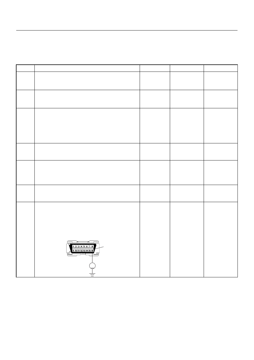
7
Using the DVM and check the data link connector
power supply circuit.
1. Ignition “Off”, engine “Off”.
2. Check the circuit for open circuit.
Was the problem found?
—
Repair faulty
harness and
verify repair
Go to Step 8
V
16
B-58