Content .. 1165 1166 1167 1168 ..
Isuzu D-Max / Isuzu Rodeo (TFR/TFS). Manual - part 1167
ELECTRICAL-BODY AND CHASSIS 8-9
Solder
Apply 60/40 rosin core solder to the opening in the back of the
clip.
Follow the manufacturer's instructions for the solder equipment
you are using.
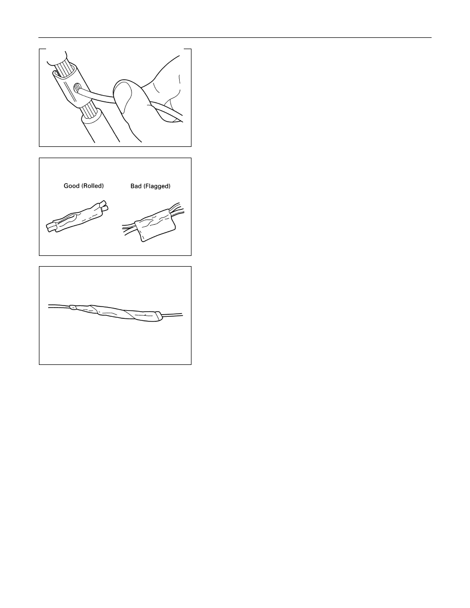
Tape the Splice
Center and roll the splicing tape.
The tape should cover the entire splice.
Roll on enough tape to duplicate the thickness of the insulation
on the existing wires.
Do not flag the tape.
Flagged tape may not provide enough insulation, and the
flagged ends will tangle with the other wires in the harness.
If the wire does not belong in a conduit or other harness
covering, tape the wire again.
Use a winding motion to cover the first piece of tape.