Isuzu D-Max / Isuzu Rodeo (TFR/TFS). Manual - part 1126


  Index      Ford     Isuzu D-Max / Isuzu Rodeo TFR/TFS series - service repair manual 1997-2003 year


Search            


Content   ..  1124  1125  1126  1127   ..


Isuzu D-Max / Isuzu Rodeo (TFR/TFS). Manual - part 1126


ELECTRICAL-BODY AND CHASSIS  8-261

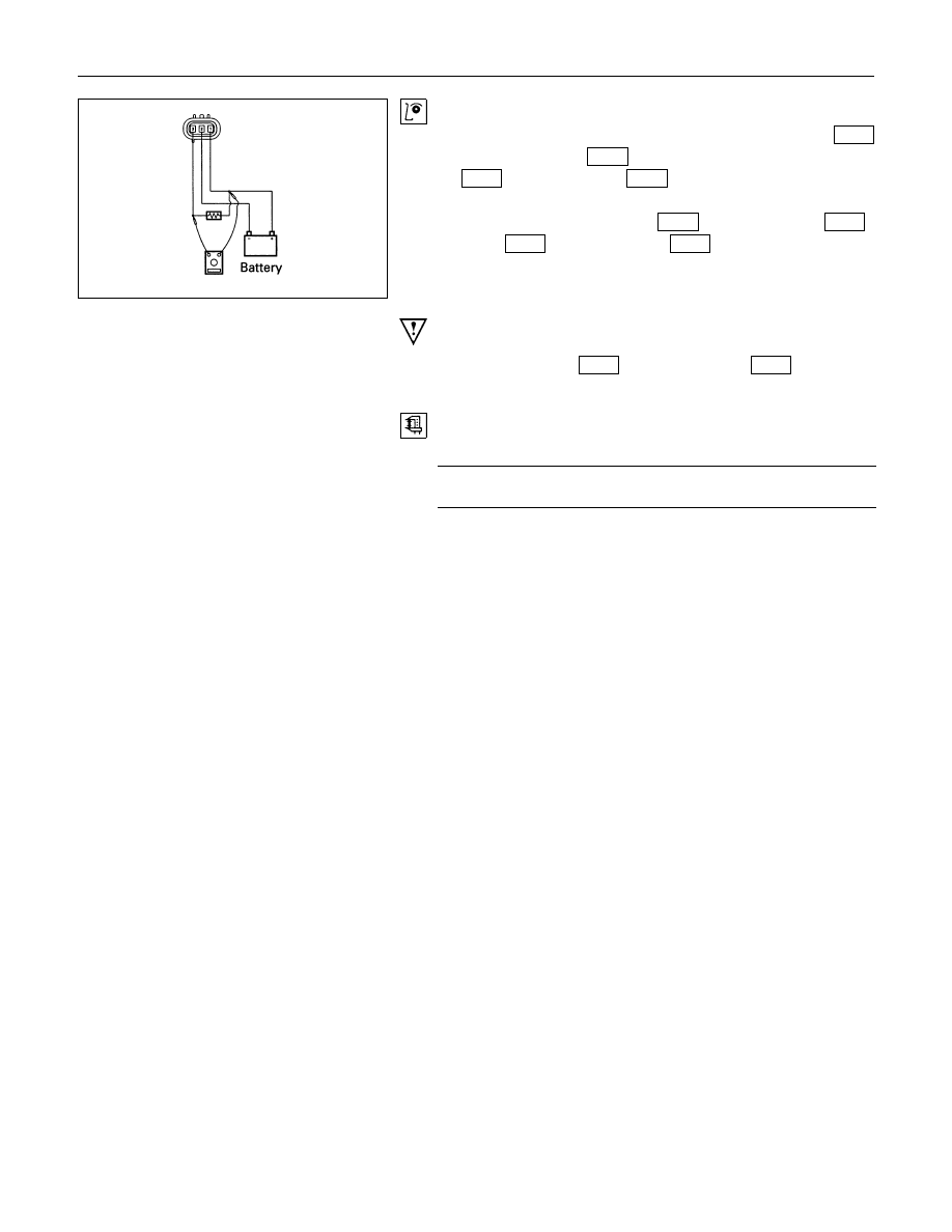
Vehicle Speed Sensor Inspection

1. Connect  the  vehicle  speed  sensor  connector  1 

M-10

(Diesel  engine:  1 

E-44

  )  to  the  battery  (+)  terminal  and  2

M-10

 (Diesel engine: 2 

E-44

 ) to the (-) terminal.

2. Connect  a  resistance  of  1.3K  ohm  to  5K  ohm  (1/4  W  or

more) between connectors 1 

M-10

. (Diesel engine: 1 

E-44

 )

and 3 

M-10

 (Diesel engine: 3 

E-44

 )

CAUTION:
Be extremely careful not to connect the battery (+) terminal
to the connector 3 

M-10

 (Diesel engine: 3 

E-44

 ).

This may damage the vehicle speed sensor.

3. Rotate  the  shaft  of  the  vehicle  speed  sensor  slowly  and

measure the voltage at the both ends with a digital tester.

The voltage, with one rotation of shaft fluctuates four times in
the following range: 10 to 14V - 2V or less.

8-262  ELECTRICAL-BODY AND CHASSIS

Timing Belt Indicator Light Reset Procedure (4 Diesel Engine)

Masking tape

A

B

W/ Tachometer

Masking tape

W/O Tachometer

A

B

Timing belt must be replaced after 100,000 km of vehicle operation.
When the odometer reading reaches 100,000 km, the timing belt indicator light will turn on to remind the driver to
change the timing belt.
After replacing the timing belt, the timing belt indicator light must be reset to remind the driver to replace the timing
belt after the next 100,000 km.

ELECTRICAL-BODY AND CHASSIS  8-263

Timing Belt Indicator Light Reset Procedure
1. Remove the masking tape from the hole

B

.

2. Remove the screw from the hole 

A

 and install it to the hole

B

.

3. Apply new masking tape to the hole 

A

.

Note:
The above procedure assumes that the timing belt is being
replaced for the first time (after 100,000 km).
For subsequent reset procedure (at next 100,000 km), hole
positions will be the opposite of the above procedure.

8-264  ELECTRICAL-BODY AND CHASSIS

HEATER AND AIR CONDITIONING

PARTS LOCATION (LHD EXCEPT EC)


Content   ..  1124  1125  1126  1127   ..