Isuzu D-Max / Isuzu Rodeo (TFR/TFS). Manual - part 66


  Index      Ford     Isuzu D-Max / Isuzu Rodeo TFR/TFS series - service repair manual 1997-2003 year


Search            


Content   ..  64  65  66  67   ..


Isuzu D-Max / Isuzu Rodeo (TFR/TFS). Manual - part 66


4JA1-TC/4JH1-TC ENGINE DRIVEABILITY AND EMISSIONS

6E–259

DIAGNOSTIC TROUBLE CODE (DTC) P1335 (SYMPTOM CODE A) 

(FLASH CODE 43) ENGINE SPEED OUTPUT CIRCUIT MALFUNCTION

Condition for setting the DTC and action taken when the DTC sets
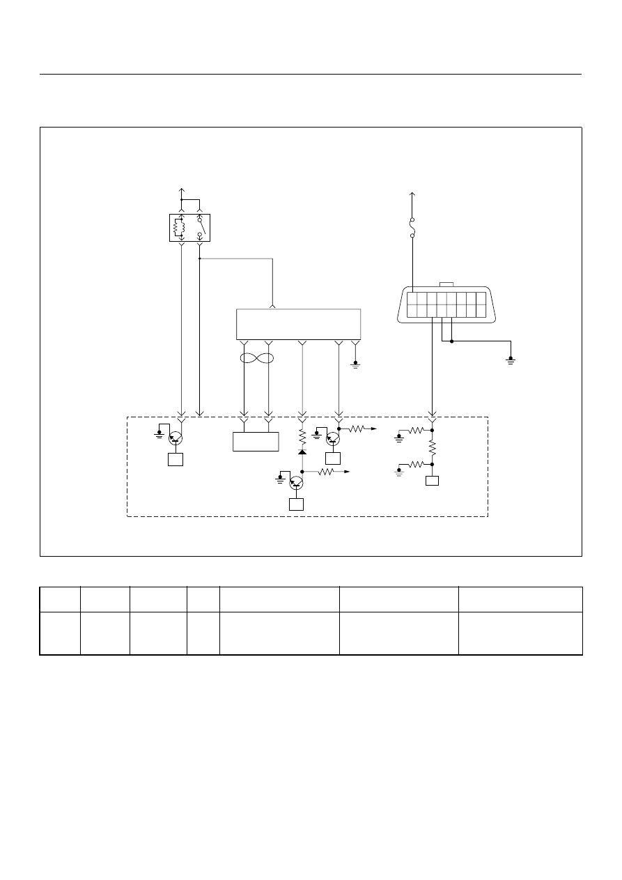
Circuit Description

The CKP sensor is located on top of the flywheel
housing of the flywheel and fixed with a bolt. The CKP
sensor is of the magnet coil type. The inductive pickup
sensors four gaps in the flywheel exciter ring and is
used to determine the engine speed and engine
cylinder top dead center.
The ECM converts sine wave signal to square wave
signal. And this signal is provided from the ECM to
pump control unit (PSG).

Diagnostic Aids

An intermittent may be caused by the following:

• Poor connections.

• Misrouted harness.

• Rubbed through wire insulation.

• Broken wire inside the insulation.
Check for the following conditions:

• Poor connection at ECM-Inspect harness connectors

for backed out terminals, improper mating, broken
locks, improperly formed or damaged terminals, and
poor terminal to wire connection.

Flash 

Code

Code

Symptom 

Code

MIL

DTC Name

DTC Setting Condition

Fail-Safe (Back Up)

43

P1335

A

ON

Engine Speed Output Circuit 
Malfunction

The PSG (pump control unit) 
is recognized defective 
engine speed signal form the 
ECM.

Fuel injection quantity is 
reduced.

45

16 15 14 13 12 11 10 9

8 7 6 5 4 3 2 1

Battery
Voltage

Battery
Voltage

0.5
RED/
YEL

2.0
BLU/
RED

7

PSG(Pump Control Unit)

Injection
Pump

2

1

5

8

0.5
WHT

2.0
BLU/
RED

0.5
BLU/
BLK

0.5
RED

0.5
ORG

100

3

58

99

105

91

0.5
PNK

6

2.0
BLK

µP

CAN
Controller

Batt

Batt

IC

µP

0.5
BLU

Stop
Light
10A

1.25
BLK

µP

Engine
Control
Module
(ECM)

ECM
Main Relay

6E–260

4JA1-TC/4JH1-TC ENGINE DRIVEABILITY AND EMISSIONS

• Damaged harness-Inspect the wiring harness for

damage. If the harness appears to be OK, observe
the  “Engine Speed” display on the Tech2 while

moving connectors and wiring harness related to the
sensor.

Diagnostic Trouble Code (DTC) P1335 (Symptom Code A) (Flash Code 43) 

Engine Speed Output Circuit Malfunction

Step

Action

Value(s)

Yes

No

1

Was the “On-Board Diagnostic (OBD) System Check”
performed?

Go to Step 2

Go to On Board 

Diagnostic 

(OBD) System 

Check

2

1. Connect the Tech 2. 

2. Review and record the failure information. 

3. Select “F0: Read DTC Infor As Stored By ECU” in

“F0: Diagnostic Trouble Codes”. 

Is the DTC P1335 (Symptom Code A) stored as
“Present Failure”?

Go to Step 3

Refer to 

Diagnostic Aids 

and Go to Step 

3

3

1. Using the Tech 2, ignition “On” and engine “Off”. 

2. Select  “F1: Clear DTC Information” in “F0:

Diagnostic Trouble Codes” with the Tech 2 and
clear the DTC information. 

3. Operate the vehicle and monitor the “F0: Read

DTC Infor As Stored By ECU” in the “F0:
Diagnostic Trouble Codes”. 

Was the DTC P1335 (Symptom Code A) stored in this
ignition cycle?

Go to Step 4

Refer to 

Diagnostic Aids 

and Go to Step 

4

4

Was the DTC P0335 (Symptom Code B) or P0335
(Symptom Code D) stored at the same time?

Go to DTC 

Chart P0335 

(Symptom 

Code B) 

(Symptom 

Code C)

Go to Step 5

5

Check for poor/faulty connection at the ECM or PSG
(pump control unit) connector. If a poor/faulty
connection is found, repair the faulty terminal. 
Was the problem found?

Verify repair

Go to Step 6

91

8

C-57(B)

E-6

4JA1-TC/4JH1-TC ENGINE DRIVEABILITY AND EMISSIONS

6E–261

6

If a oscilloscope is available, monitor the CKP sensor
output signal. Does the oscilloscope indicate correct
wave form? 

Go to Step 13

Not available: 

Go to Step 7

Fixed at low: Go 

to Step 7

Fixed at High: 

Go to Step 8

Step

Action

Value(s)

Yes

No

CKP Sensor Output Reference Wave Form

0V

Measurement Terminal: 91 (+)   1 (-)
Measurement Scale: 5.0V/div

2.0ms/div

Measurement Condition: Engine speed at 2000rpm

6E–262

4JA1-TC/4JH1-TC ENGINE DRIVEABILITY AND EMISSIONS

7

Using the DVM and check the CKP sensor output
circuit. 
Breaker box is available: 

1. Ignition “Off”, engine “Off”. 

2. Install the breaker box as type A. (ECM

disconnected) Ref. Page 6E-81 

3. Disconnect the PSG (pump control unit)

connector. 

4. Check the circuit for open or short to ground

circuit. 

Was the problem found?

Breaker box is not available: 

1. Ignition “Off”, engine “Off”. 

2. Disconnect the ECM connector. 

3. Disconnect the PSG (pump control unit)

connector. 

4. Check the circuit for open or short to ground

circuit. 

Was the problem found?

Repair faulty 
harness and 

verify repair

Go to Step 8

8

Using the DVM and check the CKP sensor output
circuit.

1. Ignition “On”, engine “Off”. 

2. Disconnect the PSG (pump control unit)

connector. 

3. Check the circuit for short to power supply circuit. 

Was the DVM indicated specified value?

Less than 1V

Go to Step 9

Repair faulty 
harness and 

verify repair

Step

Action

Value(s)

Yes

No

91

8

E-6

91

8

C-57(B)

E-6

8

V

E-6


Content   ..  64  65  66  67   ..