Isuzu D-Max / Isuzu Rodeo (TFR/TFS). Manual - part 53
4JA1-TC/4JH1-TC ENGINE DRIVEABILITY AND EMISSIONS
6E–207
Diagnostic Trouble Code (DTC) P0560 (Symptom Code A) (Flash Code 35)
System Voltage Malfunction (PSG)
Step
Action
Value(s)
Yes
No
1
Was the “On-Board Diagnostic (OBD) System Check”
performed?
—
Go to Step 2
Go to On Board
Diagnostic
(OBD) System
Check
2
1. Connect the Tech 2.
2. Review and record the failure information.
3. Select “F0: Read DTC Infor As Stored By ECU” in
“F0: Diagnostic Trouble Codes”.
Is the DTC P0560 (Symptom Code A) stored as
“Present Failure”?
—
Go to Step 3
Refer to
Diagnostic Aids
and Go to Step
3
3
1. Using the Tech 2, ignition “On” and engine “Off”.
2. Select “F1: Clear DTC Information” in “F0:
Diagnostic Trouble Codes” with the Tech 2 and
clear the DTC information.
3. Operate the vehicle and monitor the “F0: Read
DTC Infor As Stored By ECU” in the “F0:
Diagnostic Trouble Codes”.
Was the DTC P0560 (Symptom Code A) stored in this
ignition cycle?
—
Go to Step 4
Refer to
Diagnostic Aids
and Go to Step
4
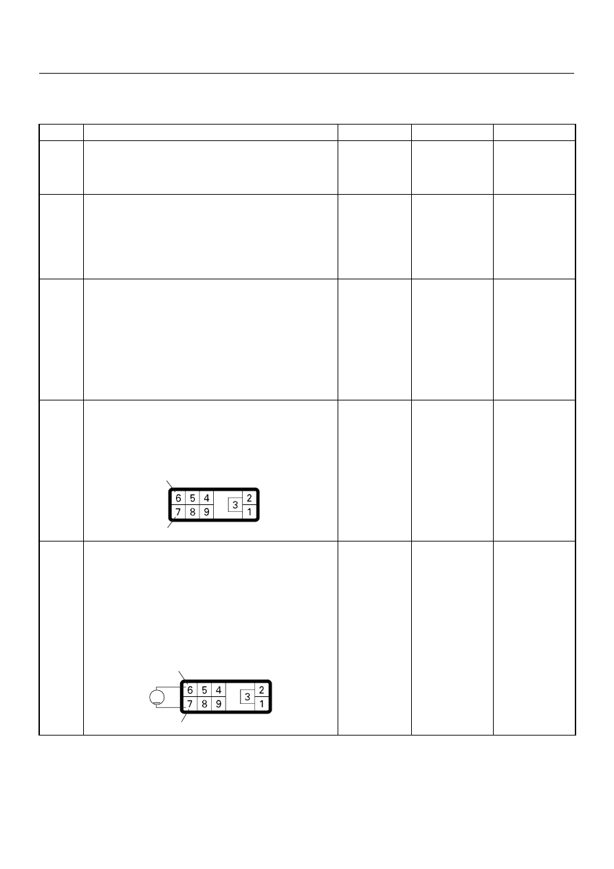
4
Check for poor/faulty connection at the PSG (pump
control unit) connector. If a poor/faulty connection is
found, repair as necessary.
Was the problem found?
—
Verify repair
Go to Step 5
5
Using the DVM and check the PSG (pump control
unit) power supply circuit.
1. Ignition “On”, engine “Off”.
2. Disconnect the PSG (pump control unit)
connector.
3. Check the PSG (pump control unit) power supply
circuit.
Was the DVM indicated specified value?
10 - 14V
Go to Step 7
Go to Step 6
6
7
E-6
6
7
V
E-6