Isuzu D-Max / Isuzu Rodeo (TFR/TFS). Manual - part 49
4JA1-TC/4JH1-TC ENGINE DRIVEABILITY AND EMISSIONS
6E–191
3
1. Using the Tech 2, ignition “On” and engine “Off”.
2. Select “F1: Clear DTC Information” in “F0:
Diagnostic Trouble Codes” with the Tech 2 and
clear the DTC information.
3. Operate the vehicle and monitor the “F0: Read
DTC Infor As Stored By ECU” in the “F0:
Diagnostic Trouble Codes”.
Was the DTC P0500 (Symptom Code 1) stored in this
ignition cycle?
—
Go to Step 4
Refer to
Diagnostic Aids
and Go to Step
4
4
Perform test drive and check the speed meter.
Does the speed meter indicate correct vehicle speed.
—
Go to Step 5
Go to Step 6
5
Perform test drive and use the Tech 2.
Monitor the “Vehicle Speed” in the data display.
Does the Tech 2 indicate correct vehicle speed as
same as the speed meter indication in the instrument
panel?
—
Go to Step 14
Go to Step 7
6
Remove the VSS from the housing case and visually
check.
Was the problem found?
—
Go to Step 8
Go to Step 7
7
Using the DVM and check the VSS signal.
1. Ignition “On”, vehicle “Run (lift up)”.
2. Measure the VSS output voltage at sensor, meter
and ECM.
Does the tester indicate specified value?
If a oscilloscope is available, monitor the VSS signal at
each connector connection. Does the oscilloscope
indicate correct wave form?
Refer to
Diagnostic Aids
and Go to Step
14
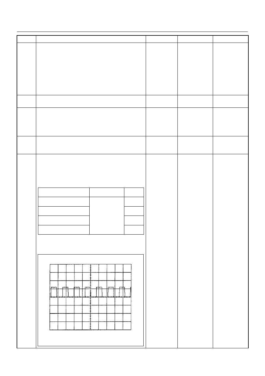
Refer the table
Step
Action
Value(s)
Yes
No
Measurement Position
Voltage (V)
(AC Range)
If No
Good
VSS terminal 3 & GND
Approximately 6.5
V at 20km/h
Go to
Step 8
Meter B23 connector 9 &
GND
Go to
Step 9
Meter B23 connector 8 &
GND
Go to
Step 11
ECM C56 connector 68 &
GND
Go to
Step 12
Vehicle Speed Sensor Reference Wave Form
0V
→
Measurement Scale: 10V/div
50ms/div
Measurement Condition: Vehicle Speed 20km/h
Measurement Terminal: At Engine Control Module