Isuzu D-Max / Isuzu Rodeo (TFR/TFS). Manual - part 28
4JA1-TC/4JH1-TC ENGINE DRIVEABILITY AND EMISSIONS
6E–107
8
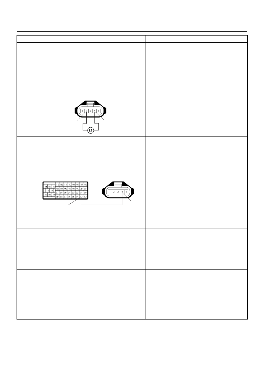
Using the DVM and check the MAF sensor power
supply circuit.
1. Ignition “Off”, engine “Off”.
2. Disconnect the MAF & IAT sensor connector and
ECM connector.
3. Check the circuit for short to MAF sensor heater
circuit.
Was the DVM indicated specified value?
No continuity
Go to Step 10
Go to Step 9
9
Repair the circuit for short to MAF sensor heater
circuit.
Is the action complete?
—
Verify repair
—
10
Repair the short to battery voltage circuit between the
ECM and MAF sensor.
Was the problem solved?
—
Verify repair
Go to Step 13
11
Substitute a known good MAF & IAT sensor assembly
and recheck.
Was the problem solved?
—
Go to Step 12
Go to Step 13
12
Replace the MAF & IAT sensor assembly.
Is the action complete?
—
Verify repair
—
13
Is the ECM programmed with the latest software
release?
If not, download the latest software to the ECM using
the “SPS (Service Programming System)”.
Was the problem solved?
—
Verify repair
Go to Step 14
14
Replace the ECM.
Is the action complete?
IMPORTANT: The replacement ECM must be
programmed. Refer to section of the Service
Programming System (SPS) in this manual.
Following ECM programming, the immobiliser system
(if equipped) must be linked to the ECM. Refer to
section 11 “Immobiliser System-ECM replacement” for
the ECM/Immobiliser linking procedure.
—
Verify repair
—
Step
Action
Value(s)
Yes
No
4
2
C-51
83
4
C-51
C-57(B)