Isuzu D-Max / Isuzu Rodeo (TFR/TFS). Manual - part 22


  Index      Ford     Isuzu D-Max / Isuzu Rodeo TFR/TFS series - service repair manual 1997-2003 year


Search            


Content   ..  20  21  22  23   ..


Isuzu D-Max / Isuzu Rodeo (TFR/TFS). Manual - part 22


4JA1-TC/4JH1-TC ENGINE DRIVEABILITY AND EMISSIONS

6E–83

ON-BOARD DIAGNOSTIC (OBD) SYSTEM CHECK

Circuit Description

The on-board diagnostic system check is the starting
point for any driveability complaint diagnosis. Before
using this procedure, perform a careful visual/physical
check of the ECM and engine grounds for cleanliness
and tightness.
The on-board diagnostic system check is an organized
approach to identifying a problem created by an
electronic engine control system   malfunction.

Diagnostic Aids

An intermittent may be caused by a poor connection,
rubbed-through wire insulation or a wire broken inside
the insulation.   Check for poor connections or a
damaged harness. Inspect the ECM harness and
connector for improper mating, broken locks, improperly
formed   or damaged terminals, poor terminal-to-wire

connection, and damaged harness.

Test Description

Number(s) below refer the step number(s) on the
Diagnostic Chart:

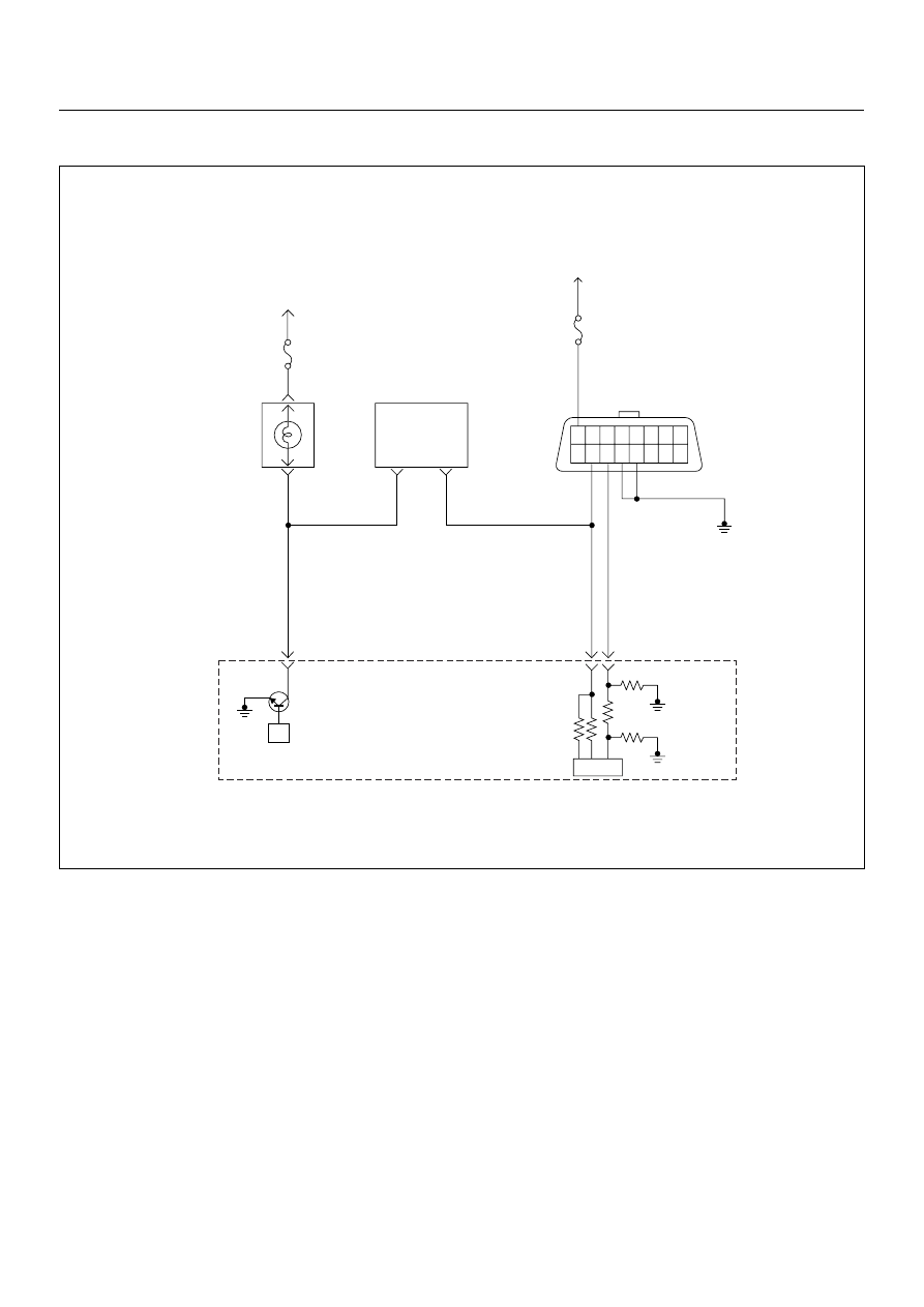
1. The Check Engine Lamp (MIL) should be ON steady
with the ignition “On”, engine “Off”. If not, “No Check
Engine Lamp (MIL)” chart should be used to isolate the
malfunction.

2. Checks the Class 2 data circuit and ensures that the
ECM is able to transmit serial data.

3. This test ensures that the ECM is capable of
controlling the Check Engine Lamp (MIL) and the Check
Engine Lamp (MIL) driver circuit is not shorted to
ground circuit.

4. If the engine will not start, “Engine Cranks But Will
Not Run” chart should be used to diagnose the fault.

µP

1.25
BLK

16 15 14 13 12 11 10 9

8 7 6 5 4 3 2 1

0.5
RED/
YEL

0.5
WHT

0.5
BLU

35

45

0.5
BRN/
YEL

42

IC

Stop
Light
10A

Meter
15A

Ignition
SW

Check
Engine
Lamp

Imnobiliser

Control Unit

Butery
Voltage

7

8

Engine
Control
Module
(ECM)

6E–84

4JA1-TC/4JH1-TC ENGINE DRIVEABILITY AND EMISSIONS

6. The Tech2 parameters which is not within the typical
range may help to isolate the area which is causing the
problem.

12. This vehicle is equipped with ECM which utilizes an
electrically erasable programmable read only memory
(EEPROM).

On-Board Diagnostic (OBD) System Check

Step

Action

Value(s)

Yes

No

1

1.  Ignition “On”, engine “Off”. 

2. Check the “CHECK ENGINE” lamp (MIL). 

Does the “CHECK ENGINE” lamp turn “On”?

Go to Step 2

Go to No 

CHECK 

ENGINE Lamp

2

1. Using the Tech 2, ignition “On” and engine “Off”. 

2. Attempt to display “Data Display” with the Tech 2. 

Does the Tech 2 display engine data? 

Go to Step 3

Go to Step 7

3

1.  Using the Tech 2, ignition “On” and engine “Off”. 

2. Select the “Miscellaneous Test” and perform the

“Check Light” in “Lamps”. 

3. Operate the Tech 2 in accordance with the Tech 2

instructions. 

Does the “CHECK ENGINE” lamp turn “Off”? 

Go to Step 4

Go to CHECK 

ENGINE LAMP 

On Steady

4

Attempt to start the engine. 
Does the engine start and continue to “Run”?

Go to Step 5

Go to Engine 

Cranks But Will 

Not Run

5

1. Using the Tech 2, ignition “On” and engine “Off”. 

2. Select the “Read DTC Infor As Stored By ECU” in

“Diagnostic Trouble Code”. 

3. Are any DTCs stored?

Go to DTC 

Chart

Go to Step 6

6

Compare typical scan data values displayed on the
Tech 2 “Data Display”. 
Are the displayed values within the range?

Refer to 

SYMPTOM 

DIAGNOSIS

Refer to 

TYPICAL 

SCAN DATA

7

Using the DVM and check the data link connector
power supply circuit.

1. Ignition “Off”, engine “Off”. 

2. Check the circuit for open circuit. 

Was the problem found?

Repair faulty 
harness and 

verify repair

Go to Step 8

V

16

C-96

4JA1-TC/4JH1-TC ENGINE DRIVEABILITY AND EMISSIONS

6E–85

8

Using the DVM and check the data link connector
ground circuit.

1. Ignition “Off”, engine “Off”. 

2. Check the circuit for open circuit. 

Was the problem found?

Repair faulty 
harness and 

verify repair

Go to Step 9

9

Using the DVM and check the data link connector
ground circuit.

1. Ignition “On”, engine “Off”. 

2. Check the circuit for short to power supply circuit. 

Was the DVM indicated specified value?

Less than 1V

Go to Step 10

Repair faulty 
harness and 

verify repair

10

Using the DVM and check the data link connector
communication circuit.

1. Ignition “On”, engine “Off”. 

2. Check the circuit for short to power supply circuit. 

Was the DVM indicated battery voltage?

Repair faulty 
harness and 

verify repair

Go to Step 11

Step

Action

Value(s)

Yes

No

5

4

C-96

V

V

5

4

C-96

V

6

C-96

6E–86

4JA1-TC/4JH1-TC ENGINE DRIVEABILITY AND EMISSIONS

11

Using the DVM and check the data link connector
communication circuit.

1. Ignition “Off”, engine “Off”. 

2. Disconnect the ECM connector. 

3. Check the circuit for open or short to ground

circuit. 

Was the problem found?

Repair faulty 
harness and 

verify repair

Go to Step 12

12

Is the ECM programmed with the latest software
release? 
If not, download the latest software to the ECM using
the “SPS (Service Programming System)”
Was the problem solved?

Verify repair

Go to Step 13

13

Replace the ECM. 
Is the action complete? 
IMPORTANT: The replacement ECM must be
programmed. Refer to section of the Service
Programming System (SPS) in this manual. 
Following ECM programming, the immobiliser system
(if equipped) must be linked to the ECM. Refer to
section 11 “Immobiliser System-ECM replacement” for
the ECM/Immobiliser linking procedure.

Verify repair

Step

Action

Value(s)

Yes

No

6

45

C-96

C-56


Content   ..  20  21  22  23   ..