Infiniti QX56 (JA60). Manual - part 360
EC-92
< COMPONENT DIAGNOSIS >
[VK56DE]
P0011, P0021 IVT CONTROL
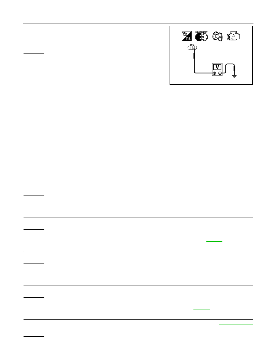
4. Check voltage between intake valve timing control solenoid
valve terminal 2 and ground with CONSULT-III or tester.
OK or NG
OK
>> GO TO 11.
NG
>> GO TO 10.
10.
DETECT MALFUNCTIONING PART
Check the following.
• Harness connectors E2, F32
• Harness for open or short between intake valve timing control solenoid valve and IPDM E/R.
>> Repair open circuit or short to ground or short to power in harness or connectors.
11.
CHECK INTAKE VALVE TIMING CONTROL SOLENOID VALVE OUTPUT SIGNAL CIRCUIT FOR OPEN
AND SHORT
1. Turn ignition switch OFF.
2. Disconnect ECM harness connector.
3. Check harness continuity between the following;
ECM terminal 10 and intake valve timing control solenoid valve (Bank 1) terminal 1 or
ECM terminal 11 and intake valve timing control solenoid valve (Bank 2) terminal 1.
Refer to Wiring Diagram.
4. Also check harness for short to ground and short to power.
OK or NG
OK
>> GO TO 12.
NG
>> Repair open circuit or short to ground or short to power in harness or connectors.
12.
CHECK INTAKE VALVE TIMING CONTROL SOLENOID VALVE
OK or NG
OK
>> GO TO 13.
NG
>> Replace malfunctioning intake valve timing control solenoid valve. Refer to
.
13.
CHECK CRANKSHAFT POSITION SENSOR (POS)
EC-203, "Component Inspection"
OK or NG
OK
>> GO TO 14.
NG
>> Replace crankshaft position sensor (POS).
14.
CHECK CAMSHAFT POSITION SENSOR (PHASE)
EC-207, "Component Inspection"
OK or NG
OK
>> GO TO 15.
NG
>> Replace malfunctioning camshaft position sensor (PHASE). Refer to
15.
CHECK CAMSHAFT SPROCKET
Check accumulation of debris to the signal pick-up portion of the camshaft sprocket. Refer to
OK or NG
OK
>> GO TO 16.
Voltage: Battery voltage
PBIB0351E
Continuity should exist.