Infiniti QX56 (JA60). Manual - part 12
B2118 TILT SENSOR
ADP-39
< COMPONENT DIAGNOSIS >
C
D
E
F
G
H
I
K
L
M
A
B
ADP
N
O
P
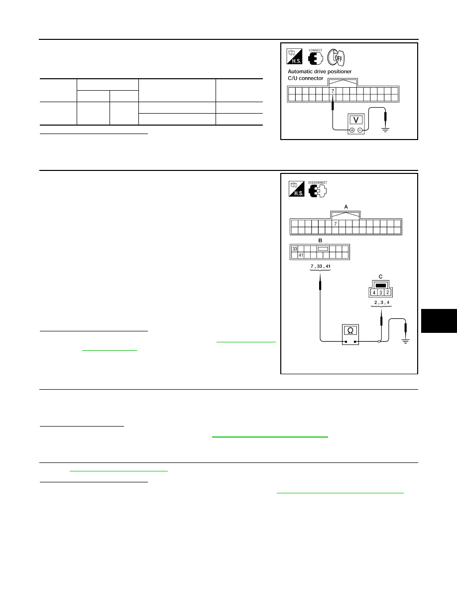
1. Turn ignition switch OFF.
2. Check voltage between automatic drive positioner connector
and ground.
Is the inspection result normal?
YES
>> Tilt sensor circuit is OK.
NO
>> GO TO 3
3.
CHECK HARNESS CONTINUITY
1. Disconnect automatic drive positioner control unit and tilt motor
assembly.
2. Check continuity between automatic drive positioner connector
M33 (A), M34 (B) terminals 7, 33, 41 and tilt motor assembly
connector M85 (C) terminals 2, 3, 4.
3. Check continuity between automatic drive positioner control unit
connectors M33 (A), M34 (B) terminals 7, 33, 41 and ground.
Is the inspection result normal?
YES
>> Replace tilt motor assembly. Refer to
.
NO
>> Repair or replace harness.
4.
CHECK DOOR MIRROR OPERATION
1. Connect automatic drive positioner control unit and tilt motor assembly.
2. Turn ignition switch ON.
3. Check door mirror operation with memory function.
Is the operation normal?
YES
>> Replace tilt motor assembly. Refer to
ST-19, "Removal and Installation"
.
NO
>> GO TO 5
5.
CHECK INTERMITTENT INCIDENT
GI-38, "Intermittent Incident"
.
Is the inspection result normal?
YES
>> Replace automatic drive positioner control unit. Refer to
ADP-175, "Removal and Installation"
.
NO
>> Repair or replace the malfunctioning part.
Connector
Terminals
Condition
Voltage (V)
(Approx.)
(+)
(-)
M33
7
Ground
Tilt top position
2
Tilt bottom position
4
LIIA0485E
7 - 3
: Continuity should exist.
33 - 2
: Continuity should exist.
41 - 4
: Continuity should exist.
7 - Ground
: Continuity should not exist.
33 - Ground
: Continuity should not exist.
41 - Ground
: Continuity should not exist.
ALJIA0291ZZ