Infiniti QX4 (R50). Manual - part 552


  Index      Infiniti     Infiniti QX4 (R50) - service repair manual 2001 year


Search            copyright infringement  


Content   ..  550  551  552  553   ..


Infiniti QX4 (R50). Manual - part 552


SST609C

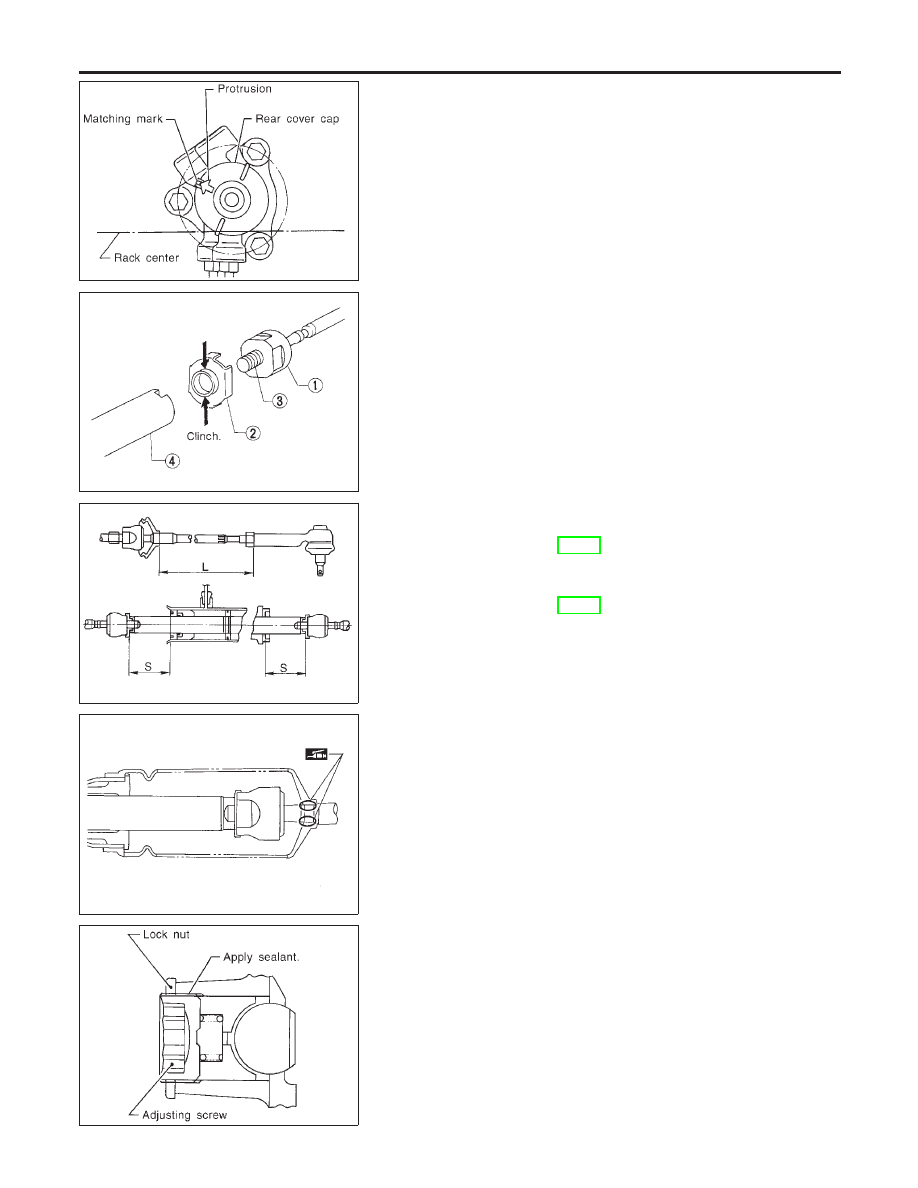
14. Ensure that the rack is centered. Install rear cover cap so that

its protrusion is positioned as shown in figure.

Be careful not to damage worm ring and oil seal.
15. Install retainer, spring and adjusting screw temporarily.

SST135C

16. Install new lock plate.

I

Attach lock plate 2 to side rod inner socket 1.

I

Apply locking sealant to inner socket threads 3.
Screw inner socket into rack 4 and tighten to specified torque.

I

Clinch two places of lock plate at rack’s groove.

CAUTION:

To prevent scratching the boot, remove burrs from lock plate.

SST655C

17. Tighten outer socket lock nut.

Tie-rod length “L”:

Refer to SDS, ST-33.

18. Measure rack stroke.

Rack stroke “S”:

Refer to SDS, ST-33.

SST967A

19. Before installing boot, coat the contact surfaces between boot

and tie-rod with grease.

SST619C

Adjustment

NBST0031

Adjust pinion rotating torque as follows:
1.

Set rack to the neutral position without fluid in the gear.

2.

Coat the adjusting screw with locking sealant and screw it in.

3.

Lightly tighten lock nut.

4.

Tighten adjusting screw to a torque of 4.9 to 5.9 N·m (50 to 60
kg-cm, 43 to 52 in-lb).

5.

Loosen adjusting screw, then retighten it to 0.2 N·m (2 kg-cm,
1.7 in-lb).

POWER STEERING GEAR AND LINKAGE

Assembly (Cont’d)

ST-24

SST718CA

6.

Move rack over its entire stroke several times.

7.

Measure pinion rotating torque within the range of 180° from
neutral position.
Stop the gear at the point of maximum torque.

8.

Loosen adjusting screw, then retighten it to 4.9 to 5.9 N·m (50
to 60 kg-cm, 43 to 52 in-lb).

9.

Loosen adjusting screw by 10° to 20°.

SST940C

10. Prevent adjusting screw from turning, and tighten lock nut to

specified torque.

SST718CA

11. Measure pinion rotating torque.

Lock to lock:

Average rotating torque

0.78 - 1.47 N·m (8.0 - 15.0 kg-cm, 6.9 - 13.0 in-lb)

Within

±

100° from the neutral position:

Maximum torque variation

0.4 N·m (4 kg-cm, 3.5 in-lb)

Outside the above range:

Maximum force variation

0.6 N·m (6 kg-cm, 5.2 in-lb)

I

If pinion rotating torque is not within specifications, readjust it
starting from step 4. If pinion rotating torque is still out of
specifications

after

readjustment,

replace

steering

gear

assembly.

SST090B

12. Check rack sliding force on vehicle as follows:
a.

Install steering gear onto vehicle, but do not connect tie-rod to
knuckle arm.

b.

Connect all piping and fill with steering fluid.

c.

Start engine and bleed air completely.

d.

Disconnect steering column lower joint from the gear.

e.

Keep engine at idle and make sure steering fluid has reached
normal operating temperature.

f.

Pull tie-rod slowly to move it from neutral position to

±

11.5 mm

(

±

0.453 in) at speed of 3.5 mm (0.138 in)/s. Check that rack

sliding force is within specification.

GI

MA

EM

LC

EC

FE

AT

TF

PD

AX

SU

BR

RS

BT

HA

SC

EL

IDX

POWER STEERING GEAR AND LINKAGE

Adjustment (Cont’d)

ST-25

Rack sliding force:

167 - 254 N (17.0 - 25.9 kg, 37 - 57 lb)

I

If rack sliding force is not within specification, readjust by
repeating adjustment procedure from the beginning.

I

If rack sliding force is still out of specification after
readjustment, gear assembly needs to be replaced.

POWER STEERING GEAR AND LINKAGE

Adjustment (Cont’d)

ST-26

Components

NBST0032

SST924C

1.

Pulley

2.

Front bracket

3.

Oil seal

4.

Suction pipe

5.

O-ring

6.

Casing

7.

Flow control valve spring

8.

Flow control A valve

9.

Dowel pin

10. Flow control B valve assembly
11. Side plate (Front)
12. Cam ring
13. Rotor
14. Vane
15. Snap ring

16. Side plate (Rear)
17. Side plate inner seal
18. Side plate outer seal
19. O-ring
20. Rear cover
21. Power steering pump bracket
22. Copper washer

SST925C

Pre-disassembly Inspection

NBST0033

Disassemble the power steering oil pump only if the following items
are found.

I

Oil leak from any point shown in the figure.

I

Deformed or damaged pulley.

I

Poor performance.

GI

MA

EM

LC

EC

FE

AT

TF

PD

AX

SU

BR

RS

BT

HA

SC

EL

IDX

POWER STEERING OIL PUMP

Components

ST-27


Content   ..  550  551  552  553   ..