Infiniti QX4 (R50). Manual - part 257
Wiring Diagram
NBEC0538
MEC981C
GI
MA
EM
LC
FE
AT
TF
PD
AX
SU
BR
ST
RS
BT
HA
SC
EL
IDX
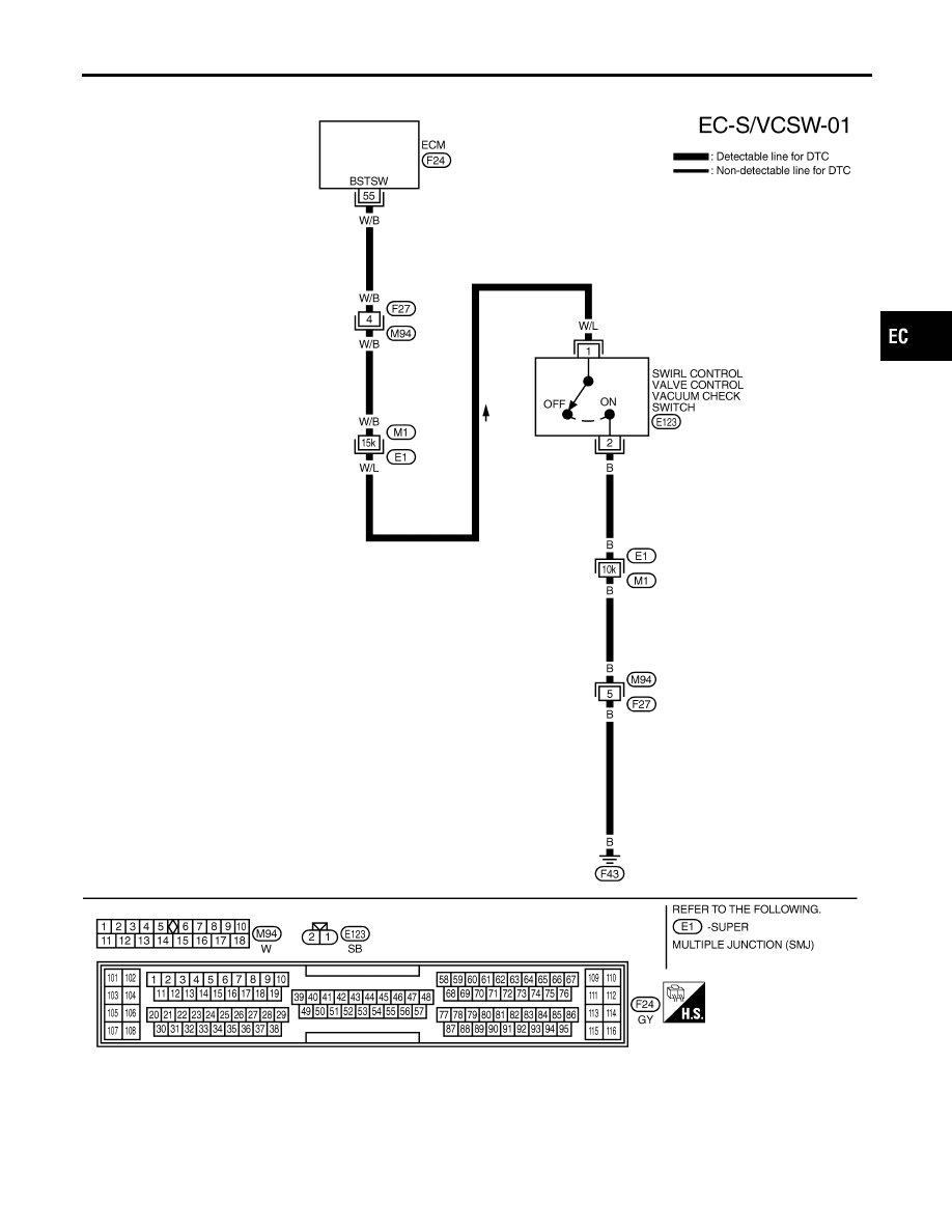
DTC P1165 SWIRL CONTROL VALVE CONTROL VACUUM CHECK SWITCH
Wiring Diagram
EC-495
|
|
|
Wiring Diagram NBEC0538 MEC981C GI MA EM LC FE AT TF PD AX SU BR ST RS BT HA SC EL IDX DTC P1165 SWIRL CONTROL VALVE CONTROL VACUUM CHECK SWITCH Wiring Diagram EC-495 |