Infiniti QX4 (R50). Manual - part 168


  Index      Infiniti     Infiniti QX4 (R50) - service repair manual 2001 year


Search            copyright infringement  


Content   ..  166  167  168  169   ..


Infiniti QX4 (R50). Manual - part 168


SEF615Z

GI

MA

EM

LC

FE

AT

TF

PD

AX

SU

BR

ST

RS

BT

HA

SC

EL

IDX

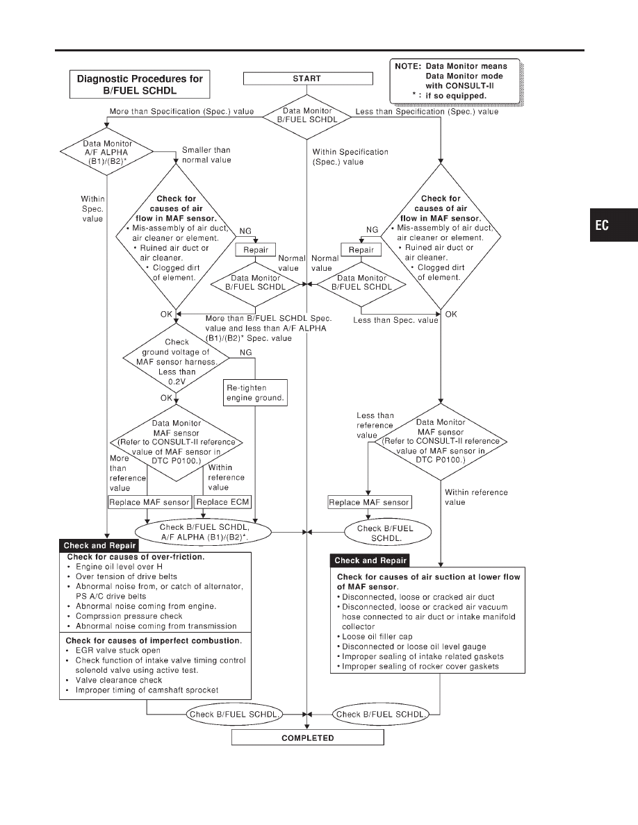
TROUBLE DIAGNOSIS — SPECIFICATION VALUE

Diagnostic Procedure (Cont’d)

EC-139

Description

NBEC0045

Intermittent incidents (I/I) may occur. In many cases, the problem resolves itself (the part or circuit function
returns to normal without intervention). It is important to realize that the symptoms described in the custom-
er’s complaint often do not recur on (1st trip) DTC visits. Realize also that the most frequent cause of I/I
occurrences is poor electrical connections. Because of this, the conditions under which the incident occurred
may not be clear. Therefore, circuit checks made as part of the standard diagnostic procedure may not indi-
cate the specific problem area.

COMMON I/I REPORT SITUATIONS

NBEC0045S01

STEP in Work Flow

Situation

II

The CONSULT-II is used. The SELF-DIAG RESULTS screen shows time data other than “0” or “[1t]”.

III

The symptom described by the customer does not recur.

IV

(1st trip) DTC does not appear during the DTC Confirmation Procedure.

VI

The Diagnostic Procedure for PXXXX does not indicate the problem area.

Diagnostic Procedure

NBEC0046

1

INSPECTION START

Erase (1st trip) DTCs. Refer to “HOW TO ERASE EMISSION — RELATED INFORMATION”, EC-72.

©

GO TO 2.

2

CHECK GROUND TERMINALS

Check ground terminals for corroding or loose connection.
Refer to GI-30, “GROUND INSPECTION”.

OK or NG

OK

©

GO TO 3.

NG

©

Repair or replace.

3

SEARCH FOR ELECTRICAL INCIDENT

Perform GI-36, “Incident Simulation Tests”.

OK or NG

OK

©

GO TO 4.

NG

©

Repair or replace.

4

CHECK CONNECTOR TERMINALS

Refer to GI-27, “How to Check Enlarged Contact Spring of Terminal”.

OK or NG

OK

©

INSPECTION END

NG

©

Repair or replace connector.

TROUBLE DIAGNOSIS FOR INTERMITTENT INCIDENT

Description

EC-140

ECM Terminals and Reference Value

NBEC0648

Specification data are reference values and are measured between each terminal and ground.

CAUTION:

Do not use ECM ground terminals when measuring input/output voltage. Doing so may result in dam-
age to the ECM’s transistor. Use a ground other than ECM terminals, such as the ground.

TERMI-

NAL

NO.

WIRE

COLOR

ITEM

CONDITION

DATA (DC Voltage)

26

L/B

ECM relay
(Self shutt-off)

[Engine is running]
[Ignition switch “OFF”]

I

For a few seconds after turning ignition switch
“OFF”

0 - 1.5V

[Ignition switch “OFF”]

I

A few seconds passed after turning ignition
switch “OFF”

BATTERY VOLTAGE
(11 - 14V)

43

R

Ignition switch

[Ignition switch “OFF”]

0V

[Ignition switch “ON”]

BATTERY VOLTAGE
(11 - 14V)

48

B

ECM ground

[Engine is running]

I

Idle speed

Engine ground
[Probe this terminal with (–)
tester probe when measuring]

57

B

ECM ground

[Engine is running]

I

Idle speed

Engine ground

12
67

W/R

Power supply for ECM
(Buck-up)

[Ignition switch “OFF”]

BATTERY VOLTAGE
(11 - 14V)

108

B

ECM ground

[Engine is running]

I

Idle speed

Engine ground

110
112

B/W
B/W

Power supply for ECM

[Ignition switch “ON”]

BATTERY VOLTAGE
(11 - 14V)

GI

MA

EM

LC

FE

AT

TF

PD

AX

SU

BR

ST

RS

BT

HA

SC

EL

IDX

TROUBLE DIAGNOSIS FOR POWER SUPPLY

ECM Terminals and Reference Value

EC-141

Main Power Supply and Ground Circuit

WIRING DIAGRAM

NBEC0047

MEC940C

TROUBLE DIAGNOSIS FOR POWER SUPPLY

Main Power Supply and Ground Circuit

EC-142


Content   ..  166  167  168  169   ..