Infiniti QX4 (R50). Manual - part 157
SEF139P
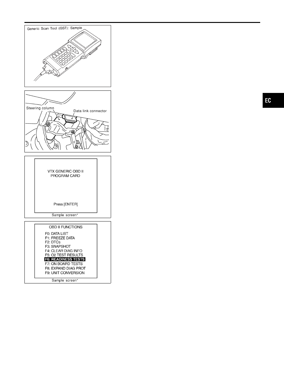
Generic Scan Tool (GST)
=NBEC0035
DESCRIPTION
NBEC0035S01
Generic Scan Tool (OBDII scan tool) complying with SAE J1978
has 8 different functions explained on the next page.
ISO9141 is used as the protocol.
The name “GST” or “Generic Scan Tool” is used in this service
manual.
SEF941Y
GST INSPECTION PROCEDURE
NBEC0035S02
1.
Turn ignition switch OFF.
2.
Connect GST to data link connector, which is located under LH
dash panel near the fuse box cover.
SEF398S
3.
Turn ignition switch ON.
4.
Enter the program according to instruction on the screen or in
the operation manual.
(*: Regarding GST screens in this section, sample screens are
shown.)
SEF416S
5.
Perform each diagnostic mode according to each service pro-
cedure.
For further information, see the GST Operation Manual of the
tool maker.
GI
MA
EM
LC
FE
AT
TF
PD
AX
SU
BR
ST
RS
BT
HA
SC
EL
IDX
ON BOARD DIAGNOSTIC SYSTEM DESCRIPTION
Generic Scan Tool (GST)
EC-95