Infiniti Q45. Manual - part 715
OIL PUMP
LU-11
C
D
E
F
G
H
I
J
K
L
M
A
LU
●
Check level of engine oil, and adjust engine oil level. Refer to
.
Disassembly and Assembly
NBS001PF
DISASSEMBLY
1.
Remove oil pump cover.
2.
Remove oil pump inner rotor and oil pump outer rotor from oil pump body.
3.
After removing regulator plug, remove regulator spring and regulator valve.
INSPECTION AFTER DISASSEMBLY
Oil Pump Clearance
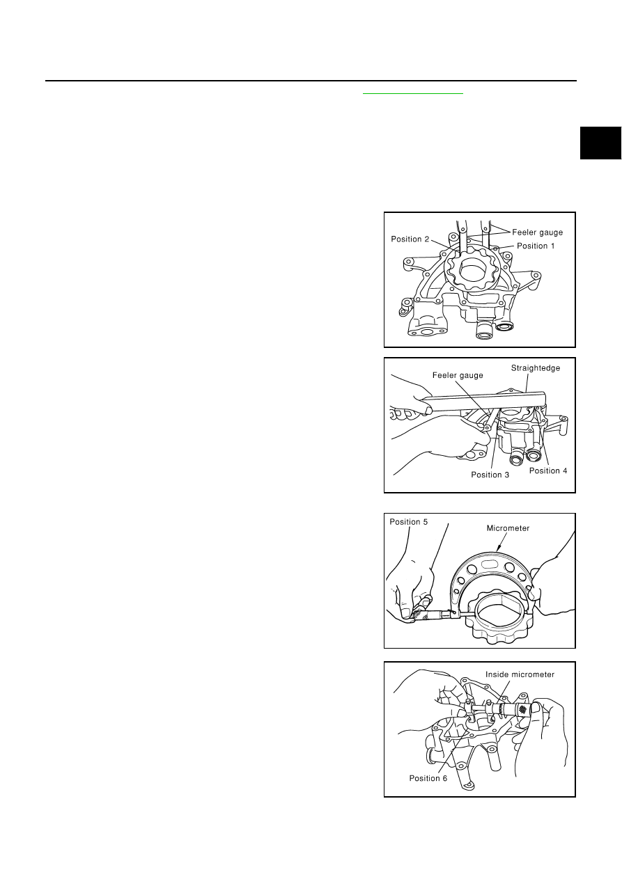
●
Measure clearance with a feeler gauge.
Clearance between oil pump outer rotor and oil pump body
(position 1)
Tip clearance between oil pump inner rotor and oil pump outer
rotor (position 2)
●
Measure clearance with a feeler gauge and a straightedge.
Side clearance between oil pump inner rotor and oil pump body
(position 3)
Side clearance between oil pump outer rotor and oil pump body
(position4)
●
Calculate the clearance between oil pump inner rotor and oil
pump body as follows:
–
Measure the outer diameter of protruded portion of oil pump
inner rotor with a micrometer (Position 5)
–
Measure the inner diameter of oil pump body with an inside
micrometer (Position 6)
•
(Clearance) = (Oil pump body inner diameter) – (Oil pump inner
rotor outer diameter)
●
If out of the standard, replace oil pump assembly.
Standard
: 0.114 - 0.200 mm (0.0045 - 0.0079 in)
Standard
: Below 0.180 mm (0.0071in)
PBIC0139E
Standard
: 0.030 - 0.070 mm (0.0012 - 0.0028 in)
Standard
: 0.030 - 0.090 mm (0.0012 - 0.0035 in)
PBIC0140E
PBIC0141E
Standard
: 0.045 - 0.091 mm (0.0018 - 0.0036 in)
PBIC0142E