Infiniti Q45. Manual - part 625


  Index      Infiniti     Infiniti Q45 - service repair manual 2006 year


Search            copyright infringement  


Content   ..  623  624  625  626   ..


Infiniti Q45. Manual - part 625


REVERSE INTERLOCK DOOR MIRROR SYSTEM

GW-93

C

D

E

F

G

H

J

K

L

M

A

B

GW

CONSULT–II Function

NIS00103

CONSULT–II executes the following functions by combining data received and command transmitted via
the communication line from BCM. IVMS communication inspection, work support (only function setting of
seats and steering wheel), self-diagnosis, data monitor, and active test display.

*: Only for function setting of seat and steering wheel

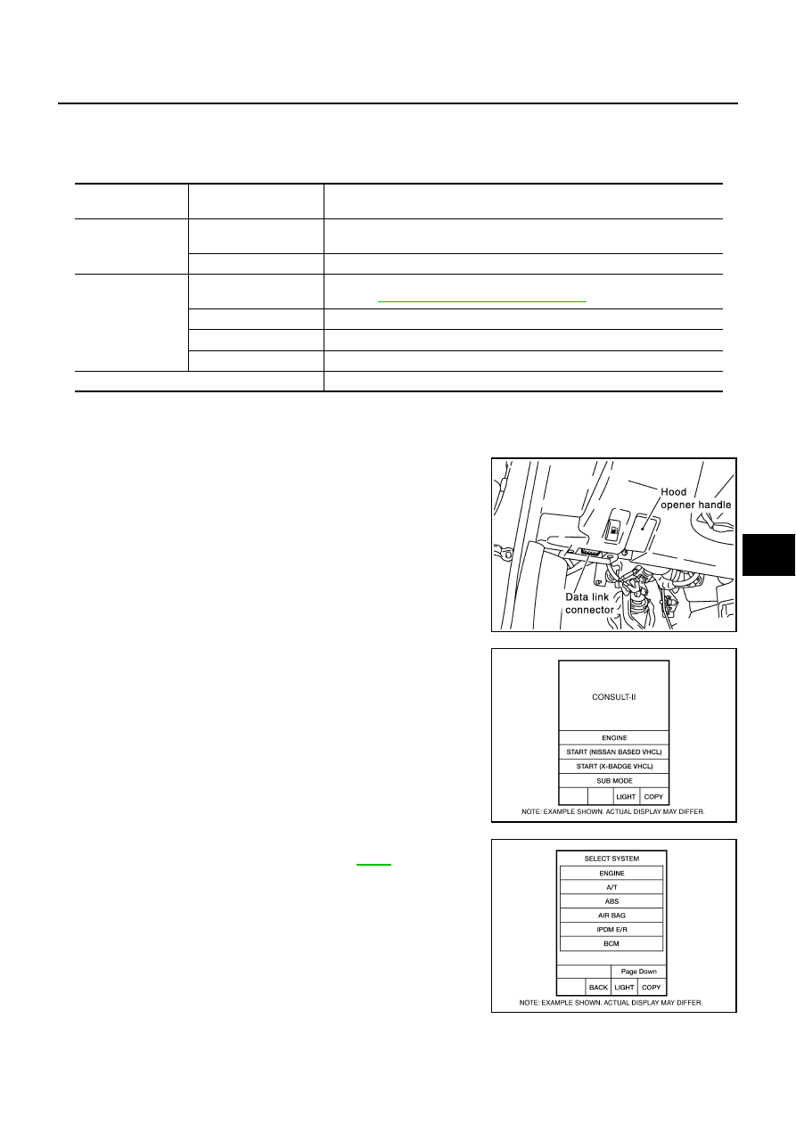
CONSULT-II BASIC OPERATION PROCEDURE

1.

Turn ignition switch “OFF”.

2.

Connect “CONSULT-II” and CONSULT-II CONVERTER to data
link connector.

3.

Turn ignition switch “ON”.

4.

Touch “START(NISSAN BASED VHCL)”.

5.

Touch “IVMS”on the “SELECT SYSTEM” screen.
If  “IVMS” is not indicated, go to Refer to 

GI-37

 ,“CONSULT-II

Date Link Connector (DLC) Circuit”.

IVMS 

diagnosis position

Inspection item and 

diagnosis mode

Description

IVMS–
COMM CHECK

IVMS–
COMM DIAGNOSIS

Diagnose a communication malfunction, inactive communication, and sleep 
malfunction in the communication line between BCM and each LCU.

WAKE–UP DIAGNOSIS

Diagnose the wake-up signals output from each LCU.

AUTO DRIVE
POSITIONER

WORK SUPPORT*

Changes the setting for each function.
 Refer to 

SE-35, "SETTING CHANGE FUNCTION"

 .

SELF–DIAG RESULTS

Carries out the self-diagnosis.

DATA MONITOR

Displays the input data of BCM and each LCU on real-time basis.

ACTIVE TEST

 Sends a drive signal to a load to check the operation.

BCM PART NUMBER

Displays BCM part No.

PBIB1069E

BCIA0029E

BCIA0030E

GW-94

REVERSE INTERLOCK DOOR MIRROR SYSTEM

6.

Check the model specification, and touch either “WITH SUN-
ROOF” or "WITHOUT SUNROOF” on the “SELECT SYS
COND" screen.

7.

Touch "OK". If the selection is wrong, touch “CANCEL”.

8.

Select the desired part to be diagnosed on the "SELECT TEST
ITEM" screen.

IVMS COMMUNICATION INSPECTION

IVMS contains the IVMS communication diagnosis and wake–up diagnosis.

IVMS Communication Diagnosis

The IVMS communication diagnosis consists of the communication diagnosis, sleep diagnosis, and inac-
tive communication diagnosis between BCM and each local unit (LCU), and display the results on the
CONSULT–II screen. 

NOTE:
Sleep is a power saving function when a vehicle is stationary (all BCM related electrical equipment: OFF,
and the timer: OFF).

The function also stores the communication malfunction records and inactive communication records, and
displays the data on the CONSULT–II screen (Malfunction record diagnosis)

*: malfunctioning item record

Operation Procedure

1.

Touch "IVMS–COMM CHECK" on "SELECT TEST ITEM" screen.

2.

Touch "IVMS–COMM DIAGNOSIS" on "SELECT DIAG ITEM" screen.

3.

Touch "START" on "IVMS–COMM DIAGNOSIS" screen to start the diagnosis.

4.

After the diagnosis is completed, the malfunctioning system is displayed.

5.

When the malfunctioning items are displayed, touch "PRINT" to record.

6.

Touch "ERASE".

7.

Carry out the communication inspection again to check that any malfunctioning item is displayed.

8.

Check the displayed items. 

Wake-Up Diagnosis

The wake-up diagnosis is carried out when BCM detects the wake-up signal from each local unit (LCU).
When the switch shown on the screen is operated as instructed, each local control unit(LCU) outputs the

PIIA0184E

Malfunction description

CONSULT–II 

display item

Description

Communication malfunction

COMM DATA

Communicating with each LCU is judged sound when the communication is 
normally completed and the transmitted data and received data are identi-
cally the same. In other cases, it is judged malfunctioning. If the communica-
tion is inactive, no diagnosis result is displayed.

Inactive communication

NO RESPONSE

Communicating with each LCU is judged sound when at least one time com-
munication is normally completed within three trials. In other cases, it is 
judged malfunctioning.

Sleep malfunction

SLEEP

Check that each LCU enters sleep mode.

Communication malfunction *

PAST COMM
DATA

The records when communication signal malfunctions were continuously 
detected while the communication was normal are displayed. Or the records 
when a malfunction is detected during the past sleep mode are displayed.

Inactive communication*

PAST NO
RESPONSE

The records when inactive communications were continuously detected 
while the communication was normal are displayed.

REVERSE INTERLOCK DOOR MIRROR SYSTEM

GW-95

C

D

E

F

G

H

J

K

L

M

A

B

GW

wake-up signal. If BCM cannot detect a wake-up signal, it is judged malfunctioning. The malfunctioning
local control unit(LCU) is displayed on the screen.

Operation Procedure

1.

Touch "IVMS–COMM CHECK" on "SELECT TEST ITEM" screen.

2.

Touch "WAKE–UP DIAGNOSIS" on "SELECT DIAG ITEM" screen.

3.

Touch "START" on "WAKE–UP DIAGNOSIS" screen to start the diagnosis.

4.

Touch "NEXT" to select the local control unit (LCU) to be diagnosed.

5.

Check that any malfunction is displayed. If necessary, touch "PRINT" to record.

6.

Carry out the inspection to the malfunctioning item.

Trouble Diagnosis Chart

NOTE:

For a specific local control unit (LCU), either "PAST COMM DATA" or "PAST NO RESPONSE" may be displayed instead of the
above results.The data record,  causes this, so erase the records.
(The display only shows the incident records, they are not malfunctions caused during the diagnosis. One possible cause is that an
intermittent incident occurred.)

Follow the steps below to erase the memory. 
Carry out either disconnect BCM battery power supply or erase memory with CONSULT-II.

Malfunctioning 

item

Display unit

CONSULT–II IVMS communication 

diagnosis content

Self-diagnosis trouble 

code No.

Malfunctioning system and 

reference

COMM DATA

One LCU
 is displayed.

POWER WINDOW  C/U–DR 
"COMM DATA"

24

Replace the displayed 
LCU.

DOOR MIRROR  C/U–RH 
"COMM DATA"

27

DOOR MIRROR  C/U–LH 
"COMM DATA"

37

POWER SEAT  C/U–DR
"COMM DATA"

47

Multiple LCUs 
are displayed

BCM
"COMM FAIL1" ,"COMM FAIL2"

Displays in order of 
24

27

37

47 and 

cycles from 24.

Communication system A: 
Refer to 

GW-96, "COM-

MUNICATION SYSTEM A"


.

NO
RESPONSE

One LCU 
is displayed.

POWER WINDOW C/U–DR 
"NO RESPONSE"

25

Communication system B: 
Refer to 

GW-96, "COM-

MUNICATION SYSTEM B"


.

DOOR MIRROR C/U–RH 
"NO RESPONSE"

28

DOOR MIRROR C/U–LH 
"NO RESPONSE"

38

POWER SEAT C/U–DR
"NO RESPONSE"

48

Multiple LCUs 
are displayed

BCM/HARNESS

Displays in order of 
25

28

38

48 and 

cycles from 25.

Communication system C: 
Refer to 

GW-96, "COM-

MUNICATION SYSTEM C"


.

SLEEP 
malfunction

One LCU 
is displayed.

POWER WINDOW C/U–DR 
"SLEEP"

No self-diagnosis 
function

Replace the displayed 
LCU.

DOOR MIRROR C/U–RH 
"SLEEP"

DOOR MIRROR C/U–LH 
"SLEEP"

POWER SEAT C/U–DR 
"SLEEP"

Multiple LCUs 
are displayed

All the above control units are dis-
played.

No self-diagnosis 
function

Communication system A: 
Refer to 

GW-96, "COM-

MUNICATION SYSTEM A"


.

GW-96

REVERSE INTERLOCK DOOR MIRROR SYSTEM

With the battery connected, if the local control unit (LCU) connector is disconnected and left for approximately 1 minute, BCM
stores "NO RESPONSE" record.

COMMUNICATION SYSTEM A

1. 

BCM INSPECTION

Replace BCM with a known-good one, and carry out the communication diagnosis. Refer to 

GW-94, "IVMS

Communication Diagnosis"

 .

OK or NG

OK

>> Replace BCM

NG

>> GO TO 2.

2. 

LCU INSPECTION

1.

Replace with the previously installed BCM.

2.

Replace LCU with a known-good one, and carry out the communication diagnosis. Refer to 

GW-94,

"IVMS Communication Diagnosis"

 .

OK or NG

OK

>> Replace LCU

NG

>> Perform the following.

Repair or replace harness.

Replace with the previously installed LCU.

COMMUNICATION SYSTEM B

1. 

HARNESS CONNECTOR INSPECTION

Check the terminals (at the control unit and harness) on the malfunctioning LCU for disconnection, bend,
loose connection, and other malfunctions.
OK or NG

OK

>> GO TO 2.

NG

>> Repair the terminals and connectors.

2. 

LCU INSPECTION

Replace the malfunctioning LCU with a known-good one, and carry out the communication diagnosis. Refer to

GW-94, "IVMS Communication Diagnosis"

 .

OK or NG

OK

>> Replace LCU

NG

>> Perform the following.

Repair or replace harness.

Replace with the previously installed LCU.

COMMUNICATION SYSTEM C

1. 

HARNESS CONNECTOR INSPECTION

Check the terminals (at the control unit and harness) on BCM and LCU for disconnection, bend, loose connc-
tion, and other malfunctions.

OK or NG

OK

>> GO TO 2.

NG

>> Repair the terminals and connectors.


Content   ..  623  624  625  626   ..