Infiniti Q45. Manual - part 612


  Index      Infiniti     Infiniti Q45 - service repair manual 2006 year


Search            copyright infringement  


Content   ..  610  611  612  613   ..


Infiniti Q45. Manual - part 612


POWER WINDOW SYSTEM

GW-41

C

D

E

F

G

H

J

K

L

M

A

B

GW

5. 

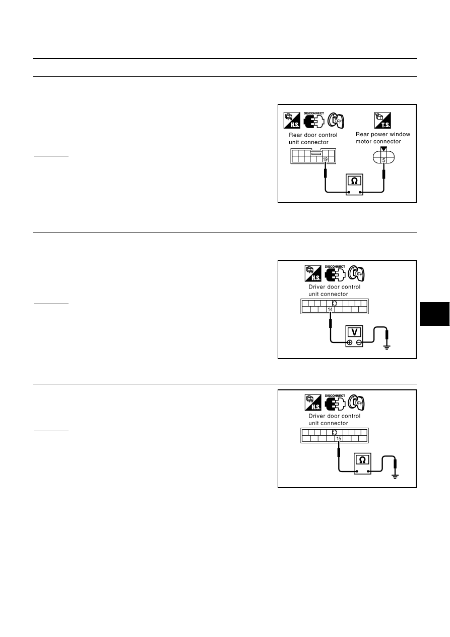
CHECK ENCODER CIRCUIT

1.

Turn ignition switch OFF.

2.

Disconnect rear door control unit LH or RH and rear power window motor LH or RH connector.

3.

Check continuity between rear door control unit LH or RH con-
nector D58(LH) or D78(RH) terminal 19 and rear power window
motor LH or RH connector D57(LH) or D77(RH) terminal 5. 

OK or NG

OK

>> Replace rear power window motor LH or RH.

NG

>> Repair or replace harness.

Check Driver Door Control Unit Circuit

NIS000Z2

1. 

POWER SUPPLY CIRCUIT CHECK

1.

Turn ignition switch OFF.

2.

Disconnect driver door control unit (LCU01) connector.

3.

Check voltage between driver door control unit (LCU01) connec-
tor D8 terminal 14 and ground.

OK or NG

OK

>> GO TO 2.

NG

>> Check the following.

40A fusible link (letter H , located in the fuse and fus-
ible link box).

Harness for open or short between driver door control
unit (LCU01) and fuse.

2. 

GROUND CIRCUIT CHECK

Check continuity between driver door control unit (LCU01) connector
D8 terminal 15 and ground.

OK or NG

OK

>> Driver door control unit circuit is OK.

NG

>> Repair or replace harness.

19 (G) – 5 (G)

:Continuity should exist.

PIIB0170E

14 (Y/G) – Ground

:Battery voltage

PIIA2703E

15 (B) – Ground

:Continuity should exist.

PIIA2704E

GW-42

POWER WINDOW SYSTEM

Check Passenger Door Control Unit Circuit

NIS000Z3

1. 

POWER SUPPLY CIRCUIT CHECK

1.

Turn ignition switch OFF.

2.

Disconnect passenger door control unit connector.

3.

Check voltage between passenger door control unit connector
D39 terminal 6 and ground.

OK or NG

OK

>> GO TO 2.

NG

>> Check the following.

40A fusible link (letter H , located in fuse and fusible
link box).

Harness for open or short between passenger door
control unit and fuse.

2. 

GROUND CIRCUIT CHECK

Check continuity between passenger door control unit connector
D39 terminal 7 and ground.

OK or NG

OK

>> GO TO 3.

NG

>> Repair or replace harness.

3. 

COMMUNICATION CIRCUIT CHECK

1.

Disconnect driver door control unit connector.

2.

Check continuity between driver door control unit connector D8
terminal 5 and passenger door control unit connector D38 termi-
nal 11.

OK or NG

OK

>> Passenger door control unit circuit is OK.

NG

>> Repair or replace harness.

6 (W/R) – Ground

:Battery voltage

PIIA3433E

7 (B) – Ground

:Continuity should exist.

PIIA3434E

5 (G/OR) – 11 (G/OR)

:Continuity should exist.

PIIA2977E

POWER WINDOW SYSTEM

GW-43

C

D

E

F

G

H

J

K

L

M

A

B

GW

Check Rear Door Control Unit Circuit

NIS000Z4

1. 

POWER SUPPLY CIRCUIT CHECK

1.

Turn ignition switch OFF.

2.

Disconnect rear door control unit LH or RH connector.

3.

Check voltage between rear door control unit LH or RH connec-
tor D59(LH) or D79(RH) terminal 6 and ground.

OK or NG

OK

>> GO TO 2.

NG

>> Check the following.

40A fusible link (letter H , located in fuse and fusible
link box).

Harness for open or short between rear door control
unit LH or RH and fuse.

2. 

GROUND CIRCUIT CHECK

Check continuity between passenger door control unit LH or RH con-
nector D59(LH) or D79(RH) terminal 7 and ground.

OK or NG

OK

>> GO TO 3.

NG

>> Repair or replace harness.

3. 

COMMUNICATION CIRCUIT CHECK

1.

Disconnect driver door control unit connector.

2.

Check continuity between driver door control unit connector D8
terminal 5 and rear door control unit LH or RH connector D58
(LH), D78 (RH) terminal 11.

OK or NG

OK

>> Rear door control unit circuit is OK.

NG

>> Repair or replace harness.

6 (Y/B) – Ground

:Battery voltage

PIIA3435E

7 (B) – Ground

:Continuity should exist.

PIIA3436E

5 (G/OR) – 11 (G/OR)

:Continuity should exist.

PIIA2977E

GW-44

POWER WINDOW SYSTEM

Check Door Switch

NIS000Z5

1. 

CHECK DOOR SWITCH INPUT SIGNAL

With CONSULT-II

Check door switch in “DATE MONITOR” mode with CONSULT-
II. Refer to 

RF-16, "DATA MONITOR"

Without CONSULT-II

Check all door switches in switch monitor mode.
Refer to Remote keyless entry system 

BL-82, "SWITCH MONI-

TOR"

 .

OK or NG

OK

>> Door switch is OK.

NG

>> GO TO 2.

2. 

CHECK DOOR SWITCH

1.

Turn ignition switch OFF.

2.

Disconnect door switch connector.

3.

Check continuity between following terminals and ground.

OK or NG

OK

>> Repair or replace following item, when there is a mal-

function.

Door switch ground condition

Harness for open or short between door switch and BCM

NG

>> Replace door switch.

When door is opened

: DOOR SW ON

When door is closed

: DOOR SW OFF

PIIA2464E

Connector

Terminals

(Wire color)

Condition

Continuity

Front door switch 
(driver side)

B20

1 (W/R)

Ground

Pressed

No

Repressed

Yes

Front door switch
(passenger side)

B220

1 (W/G)

Pressed

No

Repressed

Yes

PIIB1981E


Content   ..  610  611  612  613   ..