Infiniti Q45. Manual - part 569
CYLINDER BLOCK
EM-93
C
D
E
F
G
H
I
J
K
L
M
A
EM
c.
Put mating (with paint) on each nut and connecting rod cap, all in the same direction (when using a pro-
tractor).
d.
Then all nuts 60 degrees clockwise (angle tightening).
CAUTION:
Always use either the angle wrench (SST) or protractor.
Avoid tightening based on visual check alone.
●
After tightening the nuts, make sure that crankshaft rotates
smoothly.
●
Check the connecting rod side clearance. Refer to
"CONNECTING ROD SIDE CLEARANCE"
.
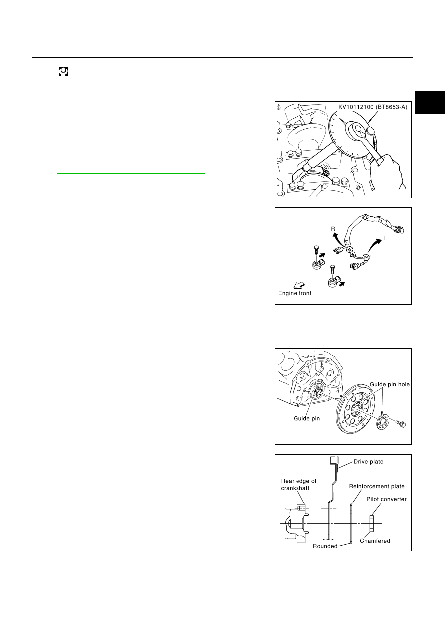
16. Install knock sensor.
●
Install it with its connector facing the rear of engine.
●
Install the sub-harness with its shorter branch line to the right
bank.
CAUTION:
●
Do not tighten mounting bolts while holding connector.
●
If any impact by dropping is applied to knock sensor,
replace it with new one.
NOTE:
●
Make sure that there is no foreign material on the cylinder
block mating surface and the back surface of knock sensor.
●
Make sure that knock sensor does not interfere with other parts.
17. Install the following in the reverse order of removal.
18. Remove engine assembly from engine stand.
19. Install drive plate.
●
Align guide pin of crankshaft rear end with pin holes of each
parts to install.
●
Install drive plate, reinforcement plate and pilot converter (if
not installed in step 4) as shown in the figure.
●
Holding ring gear with the ring gear stopper (SST: J-45476).
●
Using drift of 33 mm (1.30 in) dia, push pilot converter into the
end.
●
Face pilot converter chamfered or rounded edge side to
crankshaft.
: 14.7 N·m (1.5 kg-m, 11 ft-lb)
PBIC0104E
PBIC0105E
PBIC2867E
PBIC1965E