Infiniti Q45. Manual - part 195
POWER DOOR LOCK SYSTEM
BL-49
C
D
E
F
G
H
J
K
L
M
A
B
BL
2.
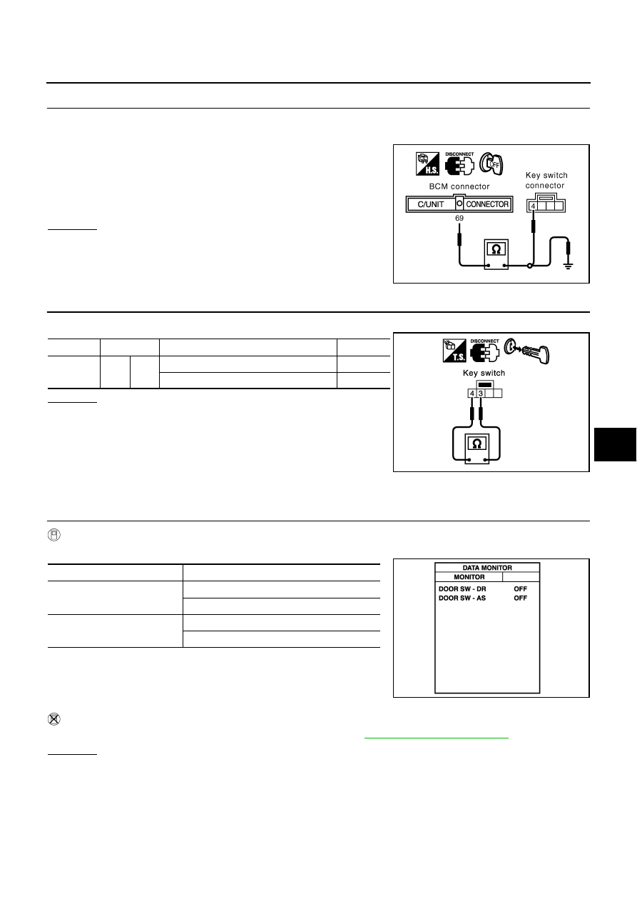
CHECK KEY SWITCH CIRCUIT
1.
Disconnect key switch connector.
2.
Check continuity between BCM connector M4 terminal 69 and key switch connector M64 terminal 4.
3.
Check continuity between BCM connector M4 terminal 69 and
ground.
OK or NG
OK
>> GO TO 3.
NG
>> Repair or replace harness.
3.
CHECK KEY SWITCH
Check continuity between key switch terminals 3 and 4.
OK or NG
OK
>> Check the following.
●
10A fuse [No. 32, located in fuse block (J/B) No. 2]
●
Harness for open or short between key switch and
fuse
NG
>> Replace key switch.
Check Front Door Switch
NIS000UA
1.
CHECK FRONT DOOR SWITCH INPUT SIGNAL
With CONSULT-II
Check front door switch (“DOOR SW-DR” and “DOOR SW-AS”) in “DATA MONITOR” mode with CONSULT-II.
Without CONSULT-II
Check front door switch in “SWITCH MONITOR” mode.Refer to
.
OK or NG
OK
>> Front door switch is OK.
NG
>> GO TO 2
69 (PU/W) – 4 (PU/W)
: Continuity should exist.
69 (PU/W) – Ground
: Continuity should not exist.
PIIA2821E
Connector
Terminal
Condition of key switch
Continuity
M64
3
4
Key is inserted in ignition key cylinder.
Yes
Key is removed from ignition key cylinder.
No
PIIA3044E
Monitor item
Condition
DOOR SW-DR
OPEN
: ON
CLOSE
: OFF
DOOR SW-AS
OPEN
: ON
CLOSE
: OFF
PIIA2464E