Infiniti Q45. Manual - part 119
TROUBLE DIAGNOSIS
ATC-71
C
D
E
F
G
H
I
K
L
M
A
B
ATC
SYSTEM DESCRIPTION
Component Parts
Mode door control system components are:
●
Auto amp.
●
Mode door motor (LCU)
●
A/C LAN system (PBR built-in mode door motor, air mix door motor and intake door motor)
●
In-vehicle sensor
●
Ambient sensor
●
Sunload sensor
●
Intake sensor
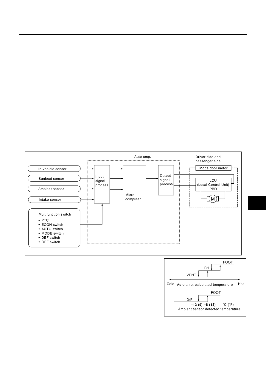
System Operation
The auto amp. receives data from each of the sensors. The auto amp. sends air mix door, mode door and
intake door opening angle data to the air mix door motor LCU, mode door motor LCU and intake door motor
LCU.
The air mix door motor, mode door motor and intake door motor read their respective signals according to the
address signal. Opening angle indication signals received from the auto amp. and each of the motor position
sensors are compared by the LCUs in each door motor with the existing decision and opening angles. Subse-
quently, HOT/COLD, DEF/VENT and FRESH/RECIRCULATION operation is selected. The new selection data
are returned to the auto amp.
Mode Door Control Specification
RJIA1287E
RHA384HA