Infiniti M35/M45 Y50. Manual - part 725


  Index      Infiniti     Infiniti M35/M45 Y50 - service repair manual 2007 year


Search            copyright infringement  


Content   ..  723  724  725  726   ..


Infiniti M35/M45 Y50. Manual - part 725


DTC P2A00, P2A03 A/F SENSOR 1

EC-1373

[VK45DE]

C

D

E

F

G

H

I

J

K

L

M

A

EC

5. 

CHECK HARNESS CONNECTOR

1.

Turn ignition switch OFF.

2.

Disconnect A/F sensor 1 harness connector.

3.

Check harness connector for water. 

OK or NG

OK

>> GO TO 6.

NG

>> Repair or replace harness connector.

6. 

CHECK A/F SENSOR 1 POWER SUPPLY CIRCUIT

1.

Turn ignition switch ON.

2.

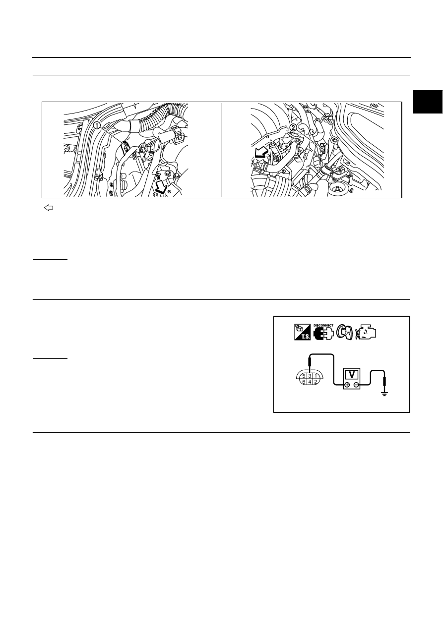
Check voltage between A/F sensor 1 terminal 3 and ground with
CONSULT-II or tester.

OK or NG

OK

>> GO TO 8.

NG

>> GO TO 7.

7. 

DETECT MALFUNCTIONING PART

Check the following.

Harness connectors E12, F3

IPDM E/R harness connector E7

15A fuse

Harness for open or short between A/F sensor 1 and fuse

>> Repair or replace harness or connectors.

: Vehicle front

1.

A/F sensor 1 (bank 2) 
harness connector

2.

A/F sensor 1 (bank 1) 
harness connector

Water should not exit.

PBIB2715E

Voltage: Battery voltage

PBIB1683E

EC-1374

[VK45DE]

DTC P2A00, P2A03 A/F SENSOR 1

8. 

CHECK A/F SENSOR 1 INPUT SIGNAL CIRCUIT FOR OPEN AND SHORT

1.

Turn ignition switch OFF.

2.

Disconnect ECM harness connector.

3.

Check harness continuity between A/F sensor 1 terminal and ECM terminal as follows.
Refer to Wiring Diagram.

4.

Check harness continuity between the following terminals and ground.
Refer to Wiring Diagram.

5.

Also check harness for short to power.

OK or NG

OK

>> GO TO 9.

NG

>> Repair open circuit or short to ground or short to power in harness or connectors.

9. 

CHECK A/F SENSOR 1 HEATER

Refer to 

EC-889, "Component Inspection"

 .

OK or NG

OK

>> GO TO 10.

NG

>> GO TO 11.

10. 

CHECK INTERMITTENT INCIDENT

Perform 

EC-857, "TROUBLE DIAGNOSIS FOR INTERMITTENT INCIDENT"

 .

OK or NG

OK

>> GO TO 11.

NG

>> Repair or replace.

A/F sensor 1 terminal

ECM terminal

Bank1

1

16

2

75

5

35

6

56

Bank 2

1

76

2

77

5

57

6

58

Continuity should exist.

Bank 1

Bank 2

A/F sensor 1 terminal

ECM terminal

A/F sensor 1 terminal

ECM terminal

1

16

1

76

2

75

2

77

5

35

5

57

6

56

6

58

Continuity should not exist.

DTC P2A00, P2A03 A/F SENSOR 1

EC-1375

[VK45DE]

C

D

E

F

G

H

I

J

K

L

M

A

EC

11. 

REPLACE AIR FUEL RATIO (A/F) SENSOR 1

Replace malfunctioning air fuel ratio (A/F) sensor 1.

CAUTION:

Discard any A/F sensor which has been dropped from a height of more than 0.5 m (19.7 in) onto a
hard surface such as a concrete floor; use a new one.

Before installing new A/F sensor, clean exhaust system threads using Oxygen Sensor Thread
Cleaner tool J-43897-18 or J-43897-12 and approved anti-seize lubricant.

>> GO TO 12.

12. 

CONFIRM A/F ADJUSTMENT DATA

1.

Turn ignition switch ON.

2.

Select “A/F ADJ-B1” and “A/F ADJ-B2” in “DATA MONITOR”
mode with CONSULT-II.

3.

Make sure that “0.000” is displayed on CONSULT-II screen.

OK or NG

OK

>> INSPECTION END

NG

>> GO TO 13.

PBIB3202E

EC-1376

[VK45DE]

DTC P2A00, P2A03 A/F SENSOR 1

13. 

CLEAR A/F ADJUSTMENT DATA

 With CONSULT-II

1.

Start engine and warm it up to normal operating temperature.

2.

Select “SELF-LEARNING CONT” in “WORK SUPPORT” mode with CONSULT-II.

3.

Clear the self-learning control coefficient by touching “CLEAR”.

 Without CONSULT-II

1.

Start engine and warm it up to normal operating temperature.

2.

Turn ignition switch OFF.

3.

Disconnect mass air flow sensor (1) harness connector.

4.

Restart engine and let it idle for at least 5 seconds.

5.

Stop engine and reconnect mass air flow sensor harness con-
nector.

6.

Make sure DTC P0102 is displayed.

7.

Erase the DTC memory. Refer to 

EC-770, "HOW TO ERASE

EMISSION-RELATED DIAGNOSTIC INFORMATION"

 .

8.

Make sure DTC P0000 is displayed.

>> GO TO 14.

14. 

CONFIRM A/F ADJUSTMENT DATA

1.

Turn ignition switch OFF and then ON.

2.

Select “A/F ADJ-B1” and “A/F ADJ-B2” in “DATA MONITOR”
mode with CONSULT-II.

3.

Make sure that “0.000” is displayed on CONSULT-II screen.

>> INSPECTION END

Removal and Installation

NBS005PJ

AIR FUEL RATIO (A/F) SENSOR 1

Refer to 

EM-183, "EXHAUST MANIFOLD AND THREE WAY CATALYST"

 .

SEF968Y

PBIB2682E

PBIB3202E


Content   ..  723  724  725  726   ..