Infiniti M35/M45 Y50. Manual - part 722


  Index      Infiniti     Infiniti M35/M45 Y50 - service repair manual 2007 year


Search            copyright infringement  


Content   ..  720  721  722  723   ..


Infiniti M35/M45 Y50. Manual - part 722


DTC P2138 APP SENSOR

EC-1361

[VK45DE]

C

D

E

F

G

H

I

J

K

L

M

A

EC

2. 

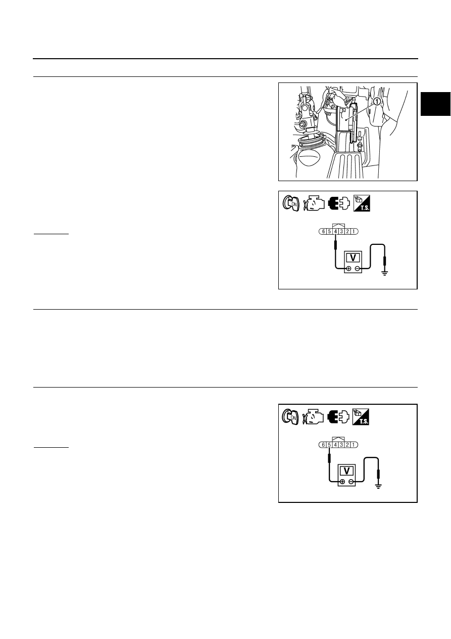
CHECK APP SENSOR 1 POWER SUPPLY CIRCUIT

1.

Disconnect accelerator pedal position (APP) sensor (1) harness
connector.

2.

Turn ignition switch ON.

3.

Check voltage between APP sensor terminal 4 and ground with
CONSULT-II or tester.

OK or NG

OK

>> GO TO 4.

NG

>> GO TO 3.

3. 

DETECT MALFUNCTIONING PART

Check the following.

Harness connectors E108, M15

Harness for open or short between ECM and accelerator pedal position sensor

>> Repair open circuit or short to ground or short to power in harness or connectors.

4. 

CHECK APP SENSOR 2 POWER SUPPLY CIRCUIT-I

1.

Turn ignition switch ON.

2.

Check voltage between APP sensor terminal 5 and ground with
CONSULT-II or tester.

OK or NG

OK

>> GO TO 10.

NG

>> GO TO 5.

PBIB2704E

Voltage: Approximately 5V

PBIA9606J

Voltage: Approximately 5V

PBIA9607J

EC-1362

[VK45DE]

DTC P2138 APP SENSOR

5. 

CHECK APP SENSOR 2 POWER SUPPLY CIRCUIT-II

1.

Turn ignition switch OFF.

2.

Disconnect ECM harness connector.

3.

Check harness continuity between APP sensor terminal 5 and ECM terminal 91.
Refer to Wiring Diagram.

OK or NG

OK

>> GO TO 7.

NG

>> GO TO 6.

6. 

DETECT MALFUNCTIONING PART

Check the following.

Harness connectors E108, M15

Harness for open or short between ECM and accelerator pedal position sensor

>> Repair open circuit.

7. 

CHECK APP SENSOR 2 POWER SUPPLY CIRCUIT-III

Check harness for short to power and short to ground, between the following terminals.

OK or NG

OK

>> GO TO 8.

NG

>> Repair short to ground or short to power in harness or connectors.

8. 

CHECK THROTTLE POSITION SENSOR

Refer to 

EC-1356, "Component Inspection"

 .

OK or NG

OK

>> GO TO 16.

NG

>> GO TO 9.

9. 

REPLACE ELECTRIC THROTTLE CONTROL ACTUATOR

1.

Replace the electric throttle control actuator.

2.

Perform 

EC-788, "Throttle Valve Closed Position Learning"

 .

3.

Perform 

EC-788, "Idle Air Volume Learning"

 .

>> INSPECTION END

Continuity should exist.

ECM terminal

Sensor terminal

Reference Wiring Diagram

91

APP sensor terminal 4

EC-1359

47

Electric throttle control actuator terminal 1

EC-1352

DTC P2138 APP SENSOR

EC-1363

[VK45DE]

C

D

E

F

G

H

I

J

K

L

M

A

EC

10. 

CHECK APP SENSOR GROUND CIRCUIT FOR OPEN AND SHORT

1.

Turn ignition switch OFF.

2.

Disconnect ECM harness connector.

3.

Check harness continuity between APP sensor terminal 2 and ECM terminal 82, APP sensor terminal 1
and ECM terminal 83.
Refer to Wiring Diagram.

4.

Also check harness for short to ground and short to power.

OK or NG

OK

>> GO TO 12.

NG

>> GO TO 11.

11. 

DETECT MALFUNCTIONING PART

Check the following.

Harness connectors E108, M15

Harness for open or short between ECM and accelerator pedal position sensor

>> Repair open circuit or short to ground or short to power in harness or connectors.

12. 

CHECK APP SENSOR INPUT SIGNAL CIRCUIT FOR OPEN AND SHORT

1.

Check harness continuity between ECM terminal 106 and APP sensor terminal 3, ECM terminal 98 and
APP sensor terminal 6.
Refer to Wiring Diagram.

2.

Also check harness for short to ground and short to power.

OK or NG

OK

>> GO TO 14.

NG

>> GO TO 13.

13. 

DETECT MALFUNCTIONING PART

Check the following.

Harness connectors E108, M15

Harness for open or short between ECM and accelerator pedal position sensor

>> Repair open circuit or short to ground or short to power in harness or connectors.

14. 

CHECK APP SENSOR

Refer to 

EC-1364, "Component Inspection"

 .

OK or NG

OK

>> GO TO 16.

NG

>> GO TO 15.

Continuity should exist.

Continuity should exist.

EC-1364

[VK45DE]

DTC P2138 APP SENSOR

15. 

REPLACE ACCELERATOR PEDAL ASSEMBLY

1.

Replace accelerator pedal assembly.

2.

Perform 

EC-788, "Accelerator Pedal Released Position Learning"

 .

3.

Perform 

EC-788, "Throttle Valve Closed Position Learning"

 .

4.

Perform 

EC-788, "Idle Air Volume Learning"

 .

>> INSPECTION END

16. 

CHECK INTERMITTENT INCIDENT

Refer to 

EC-857, "TROUBLE DIAGNOSIS FOR INTERMITTENT INCIDENT"

 .

>> INSPECTION END

Component Inspection

NBS005PB

ACCELERATOR PEDAL POSITION SENSOR

1.

Reconnect all harness connectors disconnected.

2.

Turn ignition switch ON.

3.

Check voltage between ECM terminals 106 (APP sensor 1 sig-
nal), 98 (APP sensor 2 signal) and ground under the following
conditions.

4.

If NG, replace accelerator pedal assembly and go to next step.

5.

Perform 

EC-788, "Accelerator Pedal Released Position Learning"

 .

6.

Perform 

EC-788, "Throttle Valve Closed Position Learning"

 .

7.

Perform 

EC-788, "Idle Air Volume Learning"

 .

Removal and Installation

NBS005PC

ACCELERATOR PEDAL

Refer to 

ACC-3, "ACCELERATOR CONTROL SYSTEM"

 .

Terminal

Accelerator pedal

Voltage

106
 (Accelerator pedal position 
sensor 1)

Fully released

0.4 - 1.1V

Fully depressed

3.7 - 4.8V

98
(Accelerator pedal position 
sensor 2)

Fully released

0.20 - 0.55V

Fully depressed

1.85 - 2.40V

MBIB0023E


Content   ..  720  721  722  723   ..