Infiniti M35/M45 Y50. Manual - part 601
DTC P0011, P0021 IVT CONTROL
EC-877
[VK45DE]
C
D
E
F
G
H
I
J
K
L
M
A
EC
Diagnostic Procedure
NBS005BE
1.
CHECK OIL PRESSURE WARNING LAMP
1.
Start engine.
2.
Check oil pressure warning lamp and confirm it is not illumi-
nated.
OK or NG
OK
>> GO TO 2.
KG
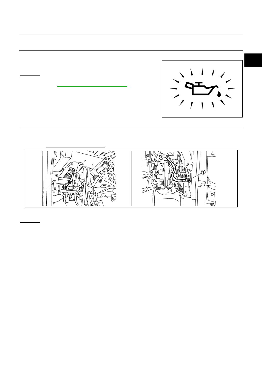
2.
CHECK GROUND CONNECTIONS
1.
Turn ignition switch OFF.
2.
Loosen and retighten ground screws on the body.
Refer to
OK or NG
OK
>> GO TO 3.
NG
>> Repair or replace ground connections.
PBIA8559J
1.
Body ground M70
2.
Body ground M16
PBIB2782E