Infiniti I35 (A33). Manual - part 487


  Index      Infiniti     Infiniti I35 (A33) - service repair manual 2004 year


Search            


Content   ..  485  486  487  488   ..


Infiniti I35 (A33). Manual - part 487


SEM926E

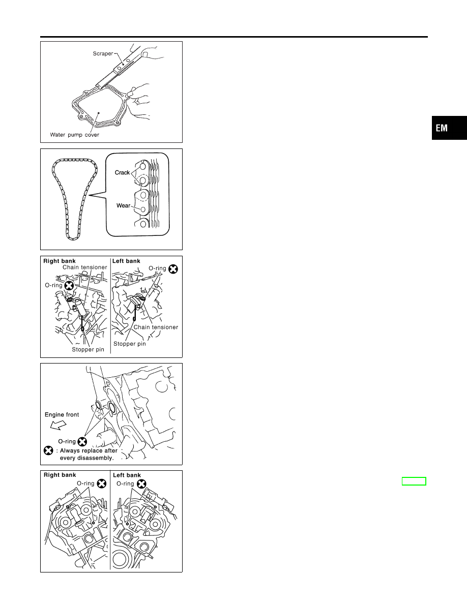
42. Use a scraper to remove all traces of liquid gasket from water

pump cover, chain tensioner cover and intake valve timing
control covers.

PBIC0282E

Inspection

NHEM0013

Check for cracks and excessive wear at roller links. Replace
chain if necessary.

SEM947G

Installation

NHEM0014

1.

Install RH and LH camshaft chain tensioners to cylinder head
as follows, if removed.

a.

Install chain tensioners with stopper pin attached and new
O-ring, if removed.

b.

Install No. 1 camshaft brackets.

PBIC0788E

2.

Install O-rings onto cylinder block.

SEM945G

3.

Install O-rings to cylinder head.

4.

Apply liquid gasket to rear timing chain case. Refer to EM-31,
“POSITION FOR APPLYING LIQUID GASKET”.

GI

MA

LC

EC

FE

AT

AX

SU

BR

ST

RS

BT

HA

SC

EL

IDX

TIMING CHAIN

Removal (Cont’d)

EM-39

SEM735G

5.

Align rear timing chain case and water pump assembly with
dowel pins (RH and LH) on cylinder block. Then install it.

I

Do not allow O-ring to drop.

a.

Tighten mounting bolts in order as shown in the figure.

I

Install two types of mounting bolts, referring to the following
instructions and figure.

Bolt length:

20 mm (0.79 in) (1, 2, 3, 6, 7, 8, 9, and 10 in the fig-
ure)
16 mm (0.63 in) (other than the above)

: 12 - 13 N·m (1.2 - 1.4 kg-m, 9 - 10 ft-lb)

b.

After all bolts are temporarily tightened, retighten them to
specified torque in order shown in the figure.

6.

After installing rear timing chain case, check surface height
difference between following parts on oil pan mounting sur-
face.

Standard

Rear timing chain case to cylinder block:

−0.24 to 0.14 mm (−0.0094 to 0.0055 in)

I

If not within standard, repeat above installation procedure.

7.

Install chain tension guide.

KBIA1073E

8.

Make sure that camshaft and crankshaft are at TDC position
of No. 1 cylinder.

I

Make sure that dowel pin hole, dowel pin and crankshaft key
are located as shown in the figure.
Camshaft dowel pin hole (intake-side): At cylinder head upper
face side in each bank
Camshaft dowel pin (exhaust-side): At cylinder head upper
face side in each bank
Crankshaft key: At cylinder head side of RH bank

CAUTION:

Hole on small diameter side must be used for intake camshaft
sprocket dowel pin. Do not misidentify (Ignore big diameter
side).

TIMING CHAIN

Installation (Cont’d)

EM-40

SEM430G

PBIC0886E

9.

Install secondary timing chain and camshaft sprocket.

CAUTION:

Matching marks between timing chain, intake and exhaust
camshaft sprockets slip easily. Confirm all matching mark
positions repeatedly during the installation process.

I

Push sleeve of secondary chain tensioner, and keep it pressed
with stopper pin.

a.

Align matching marks on secondary timing chain (gold link)
with the ones on intake and exhaust sprockets (stamped).
Then install them.

I

Matching marks of intake sprocket are on back side of second-
ary sprocket.

I

There are two types of matching marks: round and oval types.
They should be used for RH/LH banks respectively.
RH bank: Use round type.
LH bank: Use oval type.

b.

Align dowel pin and pin hole on camshaft with groove and
dowel pin on sprocket. Then install them.

I

On intake side, align pin hole on small diameter side of cam-
shaft front end with dowel pin on back side of camshaft
sprocket. Then install them.

I

On exhaust side, align dowel pin on camshaft front end with pin
groove on camshaft sprocket. Then install them.

I

Mounting bolts for camshaft sprockets must be tightened in
step 10. Tightening them by hand is enough to prevent dislo-
cation of dowel pins.

PBIC0891E

I

It may be difficult to visually check the dislocation of mating
marks during and after installation. To make the matching
easier, make a mating mark on the top of sprocket teeth and
its extended line in advance with paint.

KBIA1698J

10. After confirming the mating marks are aligned, tighten the cam-

shaft sprocket mounting bolts.

I

Secure the camshaft hexagonal portion using a spanner to
tighten mounting bolts.

GI

MA

LC

EC

FE

AT

AX

SU

BR

ST

RS

BT

HA

SC

EL

IDX

TIMING CHAIN

Installation (Cont’d)

EM-41

SEM923G

11. Pull out the stopper pin from the secondary timing chain ten-

sioner.

SEM929E

12. Install primary timing chain.

I

Install crankshaft sprocket, with matching mark to timing chain
facing front of engine.

PBIC0917E

I

Install primary timing chain so that mating mark (punched) on
camshaft sprocket is aligned with that (yellow link) on the tim-
ing chain, and mating mark (notched) on crankshaft sprocket
is aligned with that orange link on the timing chain, respec-
tively.

I

When it is difficult to align mating marks of the primary timing
chain with each sprocket, gradually turn the camshaft hexago-
nal portion using a spanner so it is aligned with the mating
mark.

TIMING CHAIN

Installation (Cont’d)

EM-42


Content   ..  485  486  487  488   ..