Infiniti I30 (A33). Manual - part 283
Wiring Diagram
NHEC0269
MEC747C
SEF629XB
GI
MA
EM
LC
FE
AT
AX
SU
BR
ST
RS
BT
HA
SC
EL
IDX
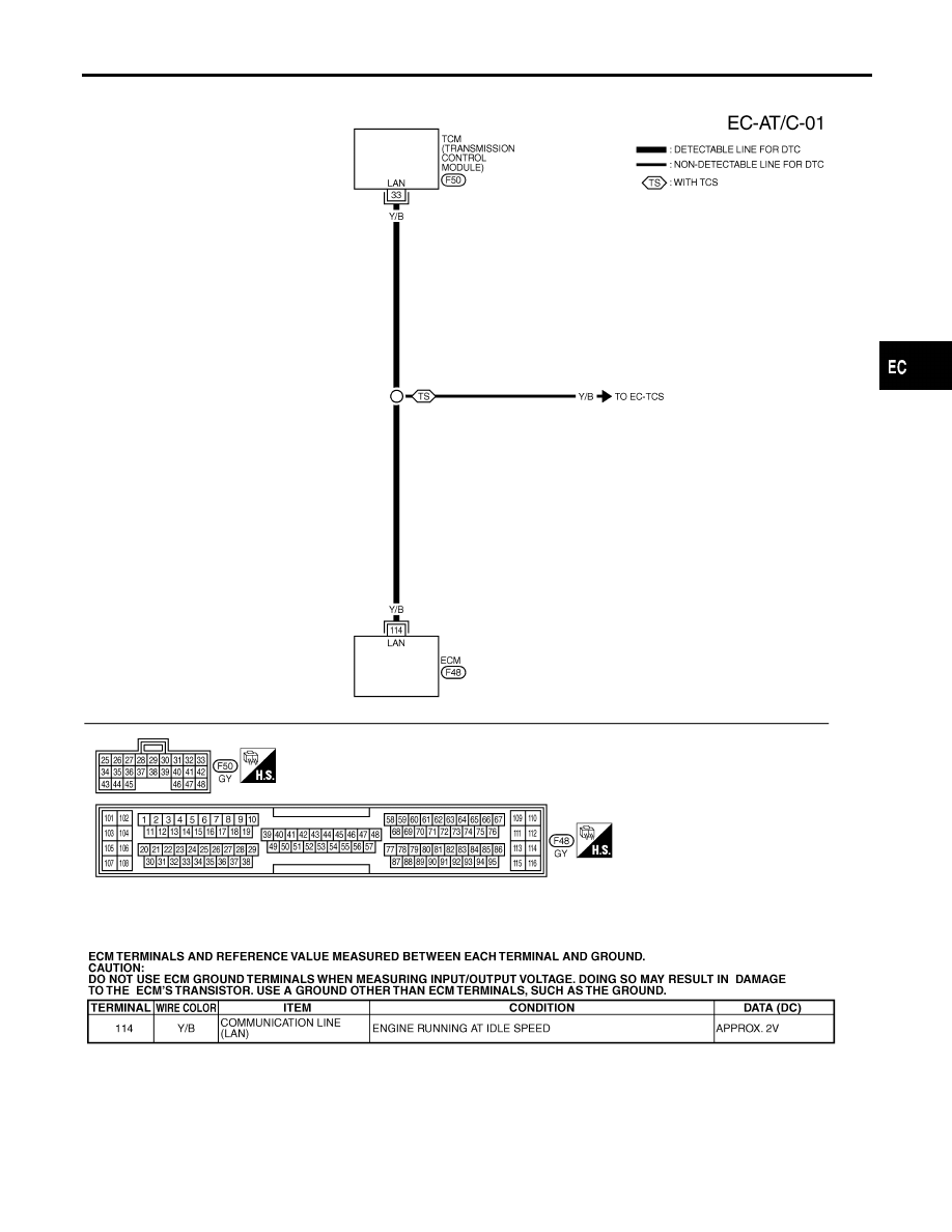
DTC P0600 A/T COMMUNICATION LINE
Wiring Diagram
EC-447
|
|
|
Wiring Diagram NHEC0269 MEC747C SEF629XB GI MA EM LC FE AT AX SU BR ST RS BT HA SC EL IDX DTC P0600 A/T COMMUNICATION LINE Wiring Diagram EC-447 |