Infiniti G35 (V35) Sedan. Manual - part 913
ENGINE MAINTENANCE
MA-17
< ON-VEHICLE MAINTENANCE >
C
D
E
F
G
H
I
J
K
L
M
B
MA
N
O
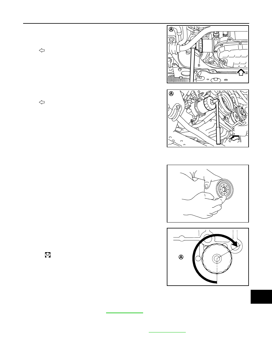
A
2.
Using oil filter wrench [SST: KV10115801 (J38956)] (B), remove
oil filter.
INSTALLATION
1.
Remove foreign materials adhering to oil filter installation surface.
2.
Apply engine oil to the oil seal contact surface of new oil filter.
3.
Screw oil filter manually until it touches the installation surface,
then tighten it by 2/3 turn (A). Or tighten to the specification.
OIL FILTER : Inspection
INFOID:0000000000967312
INSPECTION AFTER INSTALLATION
1.
Check the engine oil level. Refer to
.
2.
Start the engine, and check there is no leak of engine oil.
3.
Stop the engine and wait for 10 minutes.
4.
Check the engine oil level, and adjust the level. Refer to
.
A
: 2WD
: Engine front
JPBIA0252GB
A
: AWD
: Engine front
JPBIA0076ZZ
SMA010
Oil filter:
: 17.7 N·m (1.8 kg-m, 13 ft-lb)
JPBIA0077ZZ