Infiniti G35 (V35). Manual - part 759


  Index      Infiniti     Infiniti G35 (V35) Coupe - service repair manual 2007 year


Search            


Content   ..  757  758  759  760   ..


Infiniti G35 (V35). Manual - part 759


SE-138

FRONT SEAT

7.

Open the space between walk-in side lever and walk-in side
lever finisher.

8.

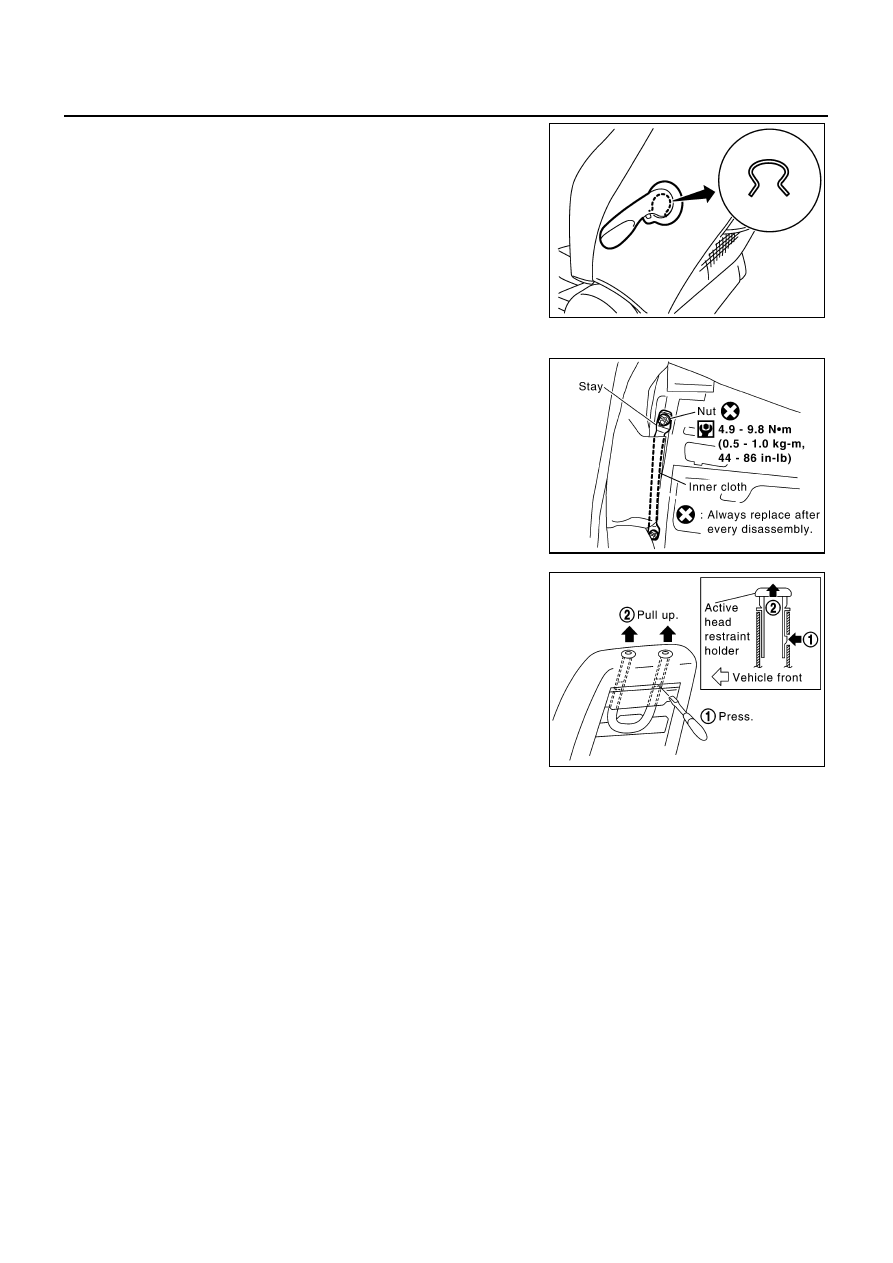
Remove snap ring, and then remove walk-in side lever.

9.

Remove screw, and then remove walk-in side lever finisher.

10. Remove the stay securing the inner cloth.

11. From the back of the seatback, press the headrest holder tab of

the stay pipe hole to disengage. Then pull the headrest holder
up to remove.

NOTE:
Before installing the headrest holder, check its orientation (front/
rear and right/left).

12. Remove the seat heater harness connector. After removing the seatback trim and pad, remove the hog

rings to separate the trim, pad and seatback heater unit.

Assembly

Assemble in the reverse order of disassembly.

REMOVAL OF SEATBACK ASSEMBLY

1.

After completing the steps 1, 2 and 3 of “SEATBACK TRIM AND PAD”, remove the harness connectors
for the side air bag from the seat cushion.

2.

Remove the reclining device mounting bolts on the seatback frame, and remove the seatback assembly.

NOTE:
When assembling the seatback frame, make sure that the reclining device are locked on both sides, and
be sure to temporarily tighten the bolts, then tighten them finally.

INSTALLATION OF SEATBACK ASSEMBLY

Install in the reverse order of removal.

SEAT CUSHION TRIM AND PAD

CAUTION:

Do not disassemble front passenger seat cushion assembly.
Always replace as an assembly.
For front passenger seat service parts, refer to the service part catalogue.

PIIB4819E

PIIA1157E

PIIA0164E

FRONT SEAT

SE-139

C

D

E

F

G

H

J

K

L

M

A

B

SE

Disassembly

1.

Pull up tabs of reclining lever knob inside. Slide knob forward to
remove.

2.

Remove the seat cushion front finisher and seat cushion outer
finisher.

3.

Remove the power seat switch assembly.

4.

Remove the retainer on the seat cushion frame, then remove the harness connector for the seat heater.

5.

After removing the seat cushion trim and pad, remove the hog rings to separate the trim and pad and the
seat cushion heater unit.

Assembly

Assemble in the reverse order of disassembly.

PIIA1161E

PIIA3805E

PIIA3656E

SE-140

REAR SEAT

REAR SEAT

PFP:88300

Removal and Installation

NIS000IP

REMOVAL

Raise the bottom of the seat cushion to release the wire from the
plastic hook, then pull the seat cushion forward to remove.

INSTALLATION

Install in the reverse order of removal.

1.

Seatback board

2.

Seatback frame

3.

Seatback device lock indicator

4.

Seatback trim

5.

Seat cushion pad

6.

Seatback device cable

7.

Seatback device lock

8.

Seat cushion trim

9.

Seat cushion pad

10. Center tray cup holder

11. Center tray box lid

12. Center tray box

PIIA3612E

SIIA0517E

SRS-1

SUPPLEMENTAL RESTRAINT SYSTEM (SRS)

H  RESTRAINTS

CONTENTS

C

D

E

F

G

I

J

K

L

M

SECTION 

A

B

SRS

SUPPLEMENTAL RESTRAINT SYSTEM (SRS)

PRECAUTIONS .......................................................... 3

Precautions for Supplemental Restraint System 
(SRS) “AIR BAG” and “SEAT BELT PRE-TEN-
SIONER” .................................................................. 3
Precautions for SRS “AIR BAG” and “SEAT BELT 
PRE-TENSIONER” Service  ..................................... 3
Precautions for Battery Service ................................ 3
Occupant Classification System Precaution  ............ 3

PREPARATION ........................................................... 4

Commercial Service Tools ........................................ 4

SUPPLEMENTAL RESTRAINT SYSTEM (SRS)  ....... 5

SRS Configuration  ................................................... 5
Front Seat Belt Pre-tensioner With Load Limiter ...... 6
Front Side Air Bag .................................................... 6
Side Curtain Air Bag ................................................. 6
Occupant Classification System (OCS)  ................... 7
Passenger Air Bag Status Condition  ........................ 7
Component Parts of Occupant Classification Sys-
tem ........................................................................... 7
Passenger Seatbelt Warning Systemlt ..................... 8

TROUBLE DIAGNOSIS .............................................. 9

Trouble Diagnosis Introduction ................................. 9

DIAGNOSIS FUNCTION ....................................... 9
HOW TO PERFORM TROUBLE DIAGNOSIS 
FOR QUICK AND ACCURATE REPAIR  ............... 9
WORK FLOW ...................................................... 10

Component Parts Location ......................................11
Schematic .............................................................. 12
Wiring Diagram — SRS —  ..................................... 13
CONSULT-II Function  ............................................ 18

DIAGNOSIS MODE FOR CONSULT-II  ............... 18
HOW TO CHANGE SELF-DIAGNOSIS MODE 
WITH CONSULT-II  .............................................. 18
HOW TO ERASE SELF-DIAGNOSTIC 
RESULTS ............................................................ 19

Self-Diagnosis Function (Without CONSULT-II) ..... 19

HOW TO CHANGE SELF-DIAGNOSIS MODE 
WITHOUT CONSULT-II  ...................................... 19
HOW TO ERASE SELF-DIAGNOSIS RESULTS 

... 19

SRS Operation Check  ............................................ 20

DIAGNOSTIC PROCEDURE 1  ........................... 20

Trouble Diagnosis with CONSULT-II  ...................... 22

DIAGNOSTIC PROCEDURE 2  ........................... 22
DIAGNOSTIC PROCEDURE 3  ........................... 27
DIAGNOSTIC PROCEDURE 4 (CONTINUED 
FROM DIAGNOSTIC PROCEDURE 2)  .............. 29
DIAGNOSTIC PROCEDURE 5  ........................... 29

Trouble Diagnosis without CONSULT-II  ................. 35

DIAGNOSTIC PROCEDURE 6  ........................... 35
WARNING LAMP FLASH CODE CHART  ........... 35

Trouble Diagnosis: “AIR BAG” Warning Lamp Does 
Not Turn OFF  ......................................................... 39

DIAGNOSTIC PROCEDURE 7  ........................... 39

Trouble Diagnosis: “AIR BAG” Warning Lamp Does 
Not Turn ON  ........................................................... 40

DIAGNOSTIC PROCEDURE 8  ........................... 40

Trouble Diagnosis: Passenger Seatbelt Warning 
System .................................................................... 41

DRIVER AIR BAG MODULE  .................................... 42

Removal and Installation  ........................................ 42

REMOVAL ........................................................... 42
INSTALLATION ................................................... 43

SPIRAL CABLE  ........................................................ 44

Removal and Installation  ........................................ 44

REMOVAL ........................................................... 44
INSTALLATION ................................................... 45

FRONT PASSENGER AIR BAG MODULE  .............. 46

Removal and Installation  ........................................ 46

REMOVAL ........................................................... 46
INSTALLATION ................................................... 46

SIDE CURTAIN AIR BAG MODULE  ........................ 47

Removal and Installation  ........................................ 47

REMOVAL ........................................................... 47
INSTALLATION ................................................... 48

CRASH ZONE SENSOR ........................................... 49

Removal and Installation  ........................................ 49

REMOVAL ........................................................... 49
INSTALLATION ................................................... 49


Content   ..  757  758  759  760   ..