Infiniti G35 (V35). Manual - part 705


  Index      Infiniti     Infiniti G35 (V35) Coupe - service repair manual 2007 year


Search            


Content   ..  703  704  705  706   ..


Infiniti G35 (V35). Manual - part 705


RFD-46

REAR FINAL DRIVE ASSEMBLY

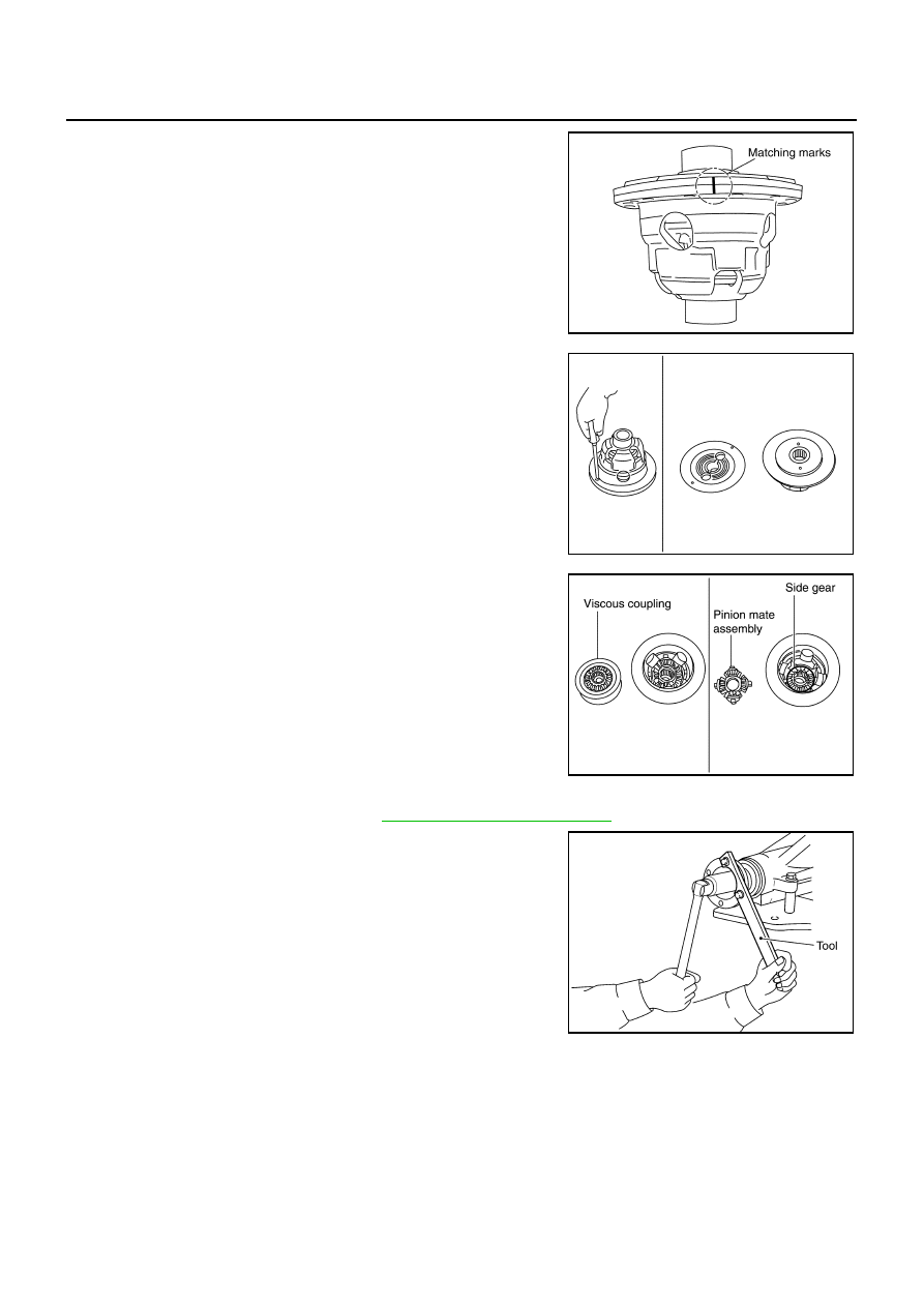
13. Put matching marks with paint.

14. Loosen screws on differential cases A and B.

15. Separate differential case A and B, then remove viscous cou-

pling, pinion mate gear, pinion mate thrust washer, side gear
and side gear thrust washer from differential cases.

Drive Pinion Assembly

1.

Remove differential assembly. Refer to 

RFD-44, "Differential Assembly"

 .

2.

Remove drive pinion lock nut with the flange wrench.

PDIA0640E

SDIA0189J

PDIA0642E

Tool number

: KV40104000 (

)

SDIA1144E

REAR FINAL DRIVE ASSEMBLY

RFD-47

C

E

F

G

H

I

J

K

L

M

A

B

RFD

3.

Put matching mark on the end of drive pinion. The matching
mark should be in line with the matching mark A on companion
flange.

CAUTION:

For matching mark, use paint. Do not damage companion
flange and drive pinion.

NOTE:
The matching mark A on the final drive companion flange indi-
cates the maximum vertical runout position.
When replacing companion flange, matching mark is not neces-
sary.

4.

Remove companion flange using the suitable puller.

5.

Press drive pinion assembly out of gear carrier.

CAUTION:

Do not drop drive pinion assembly.

6.

Remove front oil seal.

7.

Remove side oil seal.

8.

Remove pinion front bearing inner race.

9.

Remove collapsible spacer.

10. Remove pinion rear bearing inner race and drive pinion height

adjusting washer with the replacer.

11. Tap pinion front/rear bearing outer races uniformly a brass rod or

equivalent to removed.

CAUTION:

Be careful not to damage gear carrier.

PDIA0629E

SDIA1132E

SPD892

Tool number

: ST30031000 (J-22912-01)

S-PD179

SDIA0817E

RFD-48

REAR FINAL DRIVE ASSEMBLY

INSPECTION AFTER DISASSEMBLY

Clean up the disassembled parts. Then, inspect if the parts are worn or damaged. If so, follow the measures
below.

ADJUSTMENT AND SELECTION OF ADJUSTING WASHERS
Differential Side Gear Clearance

Assemble the differential parts if they are disassembled. Refer to 

RFD-55, "Differential Assembly"

 .

1.

Place differential assembly so that right side gear is on the upper side.

2.

Measure the clearance between right side gear back and differ-
ential case using feeler gauge, while rotating right side gear with
a suitable tool attached to splines.

CAUTION:

Do not place feeler gauge at groove side of differential
case.

To prevent side gear from tilting, insert feeler gauges
with the same thickness from both sides.

3.

If the back clearance is outside the specification, use a thicker/thinner side gear thrust washer to adjust.
Refer to 

RFD-60, "Side Gear Thrust Washer"

 .

CAUTION:

Adjust the clearance with the left side gear thrust washer only.

Only one side gear thrust washer can be selected.

Content

Conditions and Measures

Hypoid gear

If the gear teeth do not mesh or line-up correctly, determine the cause and adjust or replace as nec-
essary.

If the gears are worn, cracked, damaged, pitted or chipped (by friction) noticeably, replace with new 
drive gear and drive pinion as a set.

Bearing

If any chipped (by friction), pitted, worn, rusted or scratched mark, or unusual noise from the bearing 
is observed, replace as a bearing assembly (as a new set).

Side gear and Pinion mate 
gear

If any cracks or damage on the surface of the tooth is found, replace.

If any worn or chipped mark on the contact sides of the thrust washer is found, replace.

Side gear thrust washer and 
pinion mate thrust washer

If it is chipped (by friction), damaged, or unusually worn, replace.

Oil seal 

Whenever disassembled, replace.

If wear, deterioration of adherence (sealing force lips), or damage is detected on the lips, replace 
them.

Differential case

If any wear or crack on the contact sides of the differential case is found, replace.

Companion flange

If any chipped mark (about 0.1 mm, 0.004 in) or other damage on the contact sides of the lips of the 
companion flange is found, replace.

Side gear back clearance specification:

0.15 mm (0.0059 in) or less (Each gear should 
rotate smoothly without excessive resistance 
during differential motion.)

When the back clearance is large:

Use a thicker thrust washer.

When the back clearance is small:

Use a thinner thrust washer.

PDIA0641E

REAR FINAL DRIVE ASSEMBLY

RFD-49

C

E

F

G

H

I

J

K

L

M

A

B

RFD

Side Bearing Preload

Selecting of carrier side bearing adjusting washers is required for successful completion of this procedure.

1.

Make sure all parts are clean. Also, make sure the bearings are
well lubricated with gear oil.

2.

Place the differential case, with side bearings and bearing races
installed, into gear carrier.

3.

Insert left and right original side bearing adjusting washers in
place between side bearings and gear carrier.

4.

Install bearing caps in their correct locations and tighten bearing
cap mounting bolts to the specified torque. Refer to 

RFD-39,

"COMPONENTS"

 .

5.

Turn the carrier several times to seat the bearings.

6.

Measure the turning torque of the carrier at the drive gear
mounting bolts with a spring gauge.

SPD919

SPD924

PDIA0069E

Tool number

 (J-8129)

Specification:

34.2 – 39.2 N (3.5 – 4.0 kg, 7.7 – 8.8 lb) of pulling 
force at the drive gear bolt

SPD194A


Content   ..  703  704  705  706   ..