Infiniti G35 (V35). Manual - part 701
RFD-30
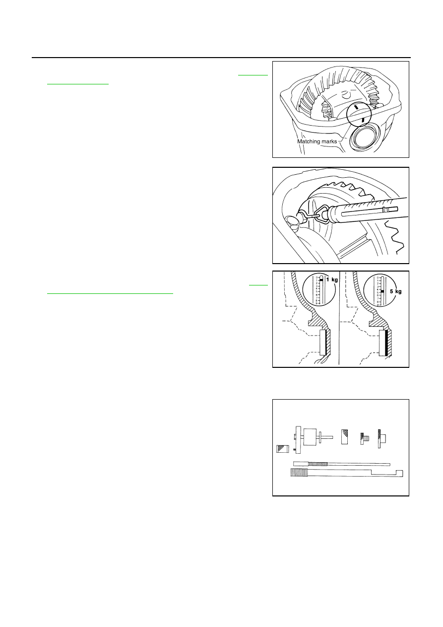
REAR FINAL DRIVE ASSEMBLY
4.
Install bearing caps in their correct locations and tighten bearing
cap mounting bolts to the specified torque. Refer to
5.
Turn the carrier several times to seat the bearings.
6.
Measure the turning torque of the carrier at the drive gear
mounting bolts with a spring gauge.
7.
If the turning torque is outside the specification, use a thicker/
thinner side bearing adjusting washer to adjust. Refer to
60, "Side Bearing Adjusting Washer"
CAUTION:
Select a side bearing adjusting washer for right and left
individually.
8.
Record the total amount of washer thickness required for the correct carrier side bearing preload.
Pinion Gear Height
1.
Make sure all parts are clean and that the bearings are well
lubricated.
2.
Assemble the pinion gear bearings into the differential shim
selector tool.
SDIA1795E
Tool number
:
—
(J-8129)
Specification:
34.2 – 39.2 N (3.5 – 4.0 kg, 7.7 – 8.8 lb) of pulling
force at the drive gear bolt
SPD194A
If the turning torque is less than the specified range:
Use a thicker thrust washer.
If the turning torque is greater than the specification:
Use a thinner thrust washer.
SPD772
Tool number
:
—
(J-34309)
SPD769