Infiniti G35 (V35). Manual - part 640


  Index      Infiniti     Infiniti G35 (V35) Coupe - service repair manual 2007 year


Search            


Content   ..  638  639  640  641   ..


Infiniti G35 (V35). Manual - part 640


MT-28

TRANSMISSION ASSEMBLY

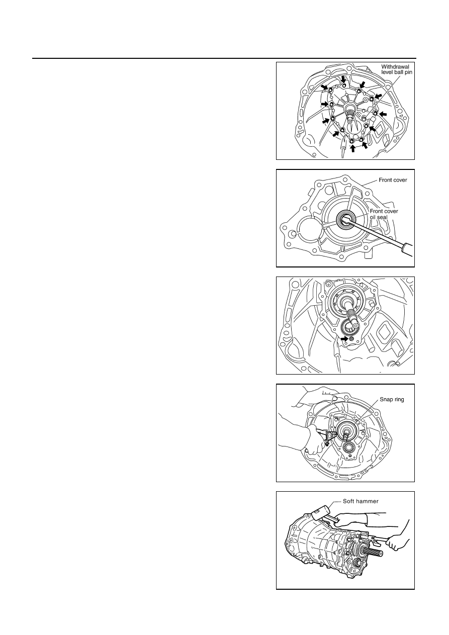
14. Remove withdrawal lever ball pin and washer from front cover.

15. Remove front cover mounting bolts. Then remove front cover

and front cover gasket from transmission case.

16. Remove front cover oil seal from front cover using a flat-bladed

screwdriver. 

CAUTION:

Be careful not to damage front cover mating surface.

17. Remove baffle plate mounting nut from transmission case.

18. Remove snap ring from main drive gear bearing using snap ring

pliers.

19. Carefully tap on transmission case to separate it from adapter

plate using a soft hummer.

PCIB0230E

PCIB0714E

SCIA1443E

PCIB0715E

SCIA1687E

TRANSMISSION ASSEMBLY

MT-29

D

E

F

G

H

I

J

K

L

M

A

B

MT

20. Remove counter front bearing from transmission case.

21. Remove oil gutter from transmission case.

Shift Control Components

1.

Install adapter setting plate to adapter plate, and then secure
adapter setting plate in a vise.

2.

Remove baffle plate mounting bolts and baffle plate from
adapter plate.

NOTE:
Mounting bolts are installed both from the front side and the
reverse side of adapter plate.

3.

Remove magnet from adapter plate.

4.

Drive out retaining pin using a pin punch [6 mm (0.24 in) dia.],
and remove striking lever and striking rod.

PCIB0436E

Tool number

: ST22490000 (

)

PCIB0254E

PCIB0716E

PCIB0414E

MT-30

TRANSMISSION ASSEMBLY

5.

Remove check ball plugs, check ball springs and check balls
from adapter plate.

6.

Remove 3rd-4th control lever mounting bolts and 3rd-4th control
lever from adapter plate.

7.

Remove shifter cap from 3rd-4th control lever.

8.

Remove check ball plug, check ball spring and check ball from
adapter plate.

9.

Drive out retaining pin using a pin punch [6mm (0.24 in) dia.],
and remove 3rd-4th fork rod bracket and 3rd-4th fork rod.

PCIB0143E

PCIB0235E

PCIB0144E

PCIB0717E

TRANSMISSION ASSEMBLY

MT-31

D

E

F

G

H

I

J

K

L

M

A

B

MT

10. Drive out retaining pin using a pin punch [6 mm (0.24 in) dia.],

and remove 3rd-4th fork rod (reversal side) and 3rd-4th shift
fork.

11. Remove check balls and interlock pin from adapter plate.

12. Drive out retaining pin using a pin punch [6 mm (0.24 in) dia.],

and remove 1st-2nd fork rod and 1st-2nd shift fork.

13. Remove interlock plunger and interlock pin from adapter plate.

14. Drive out retaining pin using a pin punch [6 mm (0.24 in) dia.],

and remove reverse fork rod and reverse shift fork.

PCIB0718E

PCIB0146E

PCIB0602E

PCIB0147E

SCIA1447E


Content   ..  638  639  640  641   ..