Infiniti G35 (V35). Manual - part 494
ENGINE ASSEMBLY
EM-131
C
D
E
F
G
H
I
J
K
L
M
A
EM
ENGINE ASSEMBLY
PFP:10001
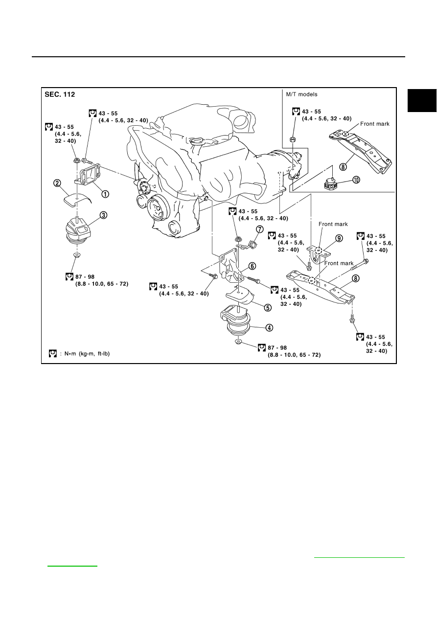
Components
NBS002V3
Removal and Installation
NBS002V4
WARNING:
●
Situate vehicle on a flat and solid surface.
●
Place chocks at front and back of rear wheels.
●
For engine not equipped with engine slingers, attach proper slingers and bolts described in
PARTS CATALOG.
CAUTION:
●
Always be careful to work safely, avoid forceful or uninstructed operations.
●
Do not start working until exhaust system and engine coolant are cool enough.
●
If items or work required are not covered by the engine section, refer to the applicable sections.
●
Always use the support point specified for lifting.
●
Use either 2-pole lift or separate type lift as best you can. If board-on lift is used for unavoidable
reasons, support at the rear axle jacking point with transmission jack or similar tool before start-
ing work, in preparation for the backward shift of center of gravity.
●
For supporting points for lifting and jacking point at rear axle. Refer to
1.
Engine mounting bracket (RH)
2.
Heat insulator (RH)
3.
Engine mounting insulator (RH)
4.
Engine mounting insulator (LH)
5.
Heat insulator (LH)
6.
Engine mounting bracket (LH)
7.
Harness bracket
8.
Rear engine mounting member
9.
Engine mounting insulator (rear)
10.
Dynamic damper
PBIC1992E