Infiniti G35 (V35). Manual - part 491


  Index      Infiniti     Infiniti G35 (V35) Coupe - service repair manual 2007 year


Search            


Content   ..  489  490  491  492   ..


Infiniti G35 (V35). Manual - part 491


CYLINDER HEAD

EM-119

C

D

E

F

G

H

I

J

K

L

M

A

EM

CYLINDER HEAD

PFP:11041

On-Vehicle Service

NBS002UX

CHECKING COMPRESSION PRESSURE

1.

Warm up engine thoroughly. Then, stop it.

2.

Release fuel pressure. Refer to 

EC-81, "FUEL PRESSURE RELEASE"
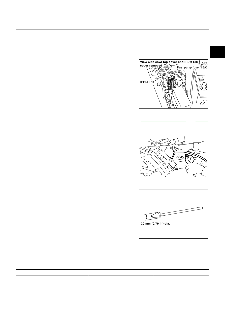
 .

3.

Disconnect fuel pump fuse to avoid fuel injection during mea-
surement.

4.

Remove engine cover with power tool. Refer to 

EM-18, "INTAKE MANIFOLD COLLECTOR"

 .

5.

Remove ignition coil and spark plug from each cylinder. Refer to 

EM-35, "IGNITION COIL"

 an

EM-36,

"SPARK PLUG (PLATINUM-TIPPED TYPE)"

 .

6.

Connect engine tachometer (not required in use of CONSULT-II).

7.

Install compression tester with adapter onto spark plug hole.

Use the adapter whose picking up end inserted to spark plug
hole is smaller than 20 mm (0.79 in) in diameter. Otherwise, it
may be caught by cylinder head during removal.

8.

With accelerator pedal fully depressed, turn ignition switch to “START” for cranking. When the gauge
pointer stabilizes, read the compression pressure and engine rpm. Perform these steps to check each cyl-
inder.

Compression pressure:

Unit: kPa (kg/cm

2

 , psi) /rpm

CAUTION:

Always use a fully changed battery to obtain specified engine speed.

PBIB1910E

PBIC0900E

SBIA0533E

Standard

Minimum

Differential limit between cylinders

 1,270 (13.0, 184)/300

980 (10.0, 142)/300

100 (1.0, 15)/300

EM-120

CYLINDER HEAD

If the engine speed is out of specified range, check battery liquid for proper gravity. Check engine
speed again with normal battery gravity. 

If compression pressure is below minimum value, check valve clearances and parts associated with
combustion chamber (valve, valve seat, piston, piston ring, cylinder bore, cylinder head, cylinder head
gasket). After the checking, measure compression pressure again.

If some cylinders have low compression pressure, pour small amount of engine oil into the spark plug
hole of the cylinder to re-check it for compression.

If the added engine oil improves the compression, piston rings may be worn out or damaged. Check the
piston rings and replace if necessary.

If the compression pressure remains at low level despite the addition of engine oil, valves may be mal-
functioning. Check valves for damage. Replace valve or valve seat accordingly.

If two adjacent cylinders have respectively low compression pressure and their compression remains
low even after the addition of engine oil, cylinder head gaskets are leaking. In such a case, replace cyl-
inder head gaskets.

9.

After inspection is completed, install removed parts.

10. Start engine, and make sure that engine runs smoothly.
11. Perform trouble diagnosis. If DTC appears, erase it. Refer to 

EC-83, "TROUBLE DIAGNOSIS"

 .

Components

NBS002UY

Removal and Installation

NBS002UZ

REMOVAL

1.

Remove camshaft. Refer to 

EM-100, "CAMSHAFT"

 .

NOTE:
It is also possible to perform the following steps 2 and 3 just before removing the camshaft.

1.

Engine rear lower slinger 

2.

Cylinder head (left bank)

3.

Cylinder head bolt

4.

Cylinder head (right bank)

5.

Cylinder head gasket (right bank)

6.

Cylinder head gasket (left bank)

7.

Oil level gauge guide

PBIC1927E

CYLINDER HEAD

EM-121

C

D

E

F

G

H

I

J

K

L

M

A

EM

2.

Temporarily fit front suspension member to support engine. Refer to 

FSU-19, "FRONT SUSPENSION

MEMBER"

 .

CAUTION:

Temporary fitting means the status that engine is adequately stable though the hoist is released
from hanging.

NOTE:
At the time of the start of this procedure front suspension member is removed, and cylinder head is
hanged by the hoist with engine slinger installed.

3.

Release the hoist from hanging, then remove the engine slinger.

4.

Remove the following components and related parts:

Fuel tube and fuel injector assembly: Refer to 

EM-38, "FUEL INJECTOR AND FUEL TUBE"

 .

Intake manifold: Refer to 

EM-23, "INTAKE MANIFOLD"

 .

Exhaust manifold: Refer to 

EM-25, "EXHAUST MANIFOLD AND THREE WAY CATALYST"

 .

Water inlet and thermostat assembly: Refer to 

CO-28, "WATER INLET AND THERMOSTAT ASSEM-

BLY"

 .

Water outlet and water pipe: Refer to 

CO-30, "WATER OUTLET AND WATER PIPING"

 .

5.

Remove cylinder head bolts in reverse order as shown in the fig-
ure with cylinder head bolt wrench (commercial service tool) and
power tool. 

6.

Remove cylinder head gaskets.

INSPECTION AFTER REMOVAL
Cylinder Head Bolts Outer Diameter

Cylinder head bolts are tightened by plastic zone tightening
method. Whenever the size difference between “d1” and “d2”
exceeds the limit, replace them with new one. 

If reduction of outer diameter appears in a position other than
“d2”, use it as “d2” point.

PBIC2057E

Limit (“d1” - “d2”)

: 0.11 mm (0.0043 in)

SEM957E

EM-122

CYLINDER HEAD

Cylinder Head Distortion

NOTE:
When performing this inspection, cylinder block distortion should be also checked. Refer to 

EM-160, "CYLIN-

DER BLOCK DISTORTION"

 .

1.

Using scraper, wipe off oil, scale, gasket, sealant and carbon deposits from surface of cylinder head.

CAUTION:

Do not allow gasket fragments to enter engine oil or engine coolant passages.

2.

At each of several locations on bottom surface of cylinder head,
measure the distortion in six directions.

If it exceeds the limit, replace cylinder head.

INSTALLATION

1.

Install new cylinder head gasket.

2.

Turn crankshaft until No. 1 piston is set at TDC.

Crankshaft key should line up with the right bank cylinder cen-
ter line as shown in the figure.

3.

Install cylinder head follow the steps below to tighten cylinder
head bolts in numerical order as shown in the figure.

CAUTION:

If cylinder head bolts re–used, check their outer diameters-
before installation. Refer to 

EM-121, "Cylinder Head Bolts

Outer Diameter"

a.

Apply new engine oil to threads and seat surfaces of cylinder
head bolts.

b.

Tighten all bolts.

c.

Completely loosen.

CAUTION:

In step “b”, loosen bolts in reverse order of that indicated in
the figure.

d.

Tighten all bolts.

Limit

: 0.1 mm (0.004 in)

SEM861E

SEM532G

 : 98.1 N·m (10 kg-m, 72 ft-lb)

 : 0 N·m (0 kg-m, 0 ft-lb)

 : 34.3 - 44.1 N·m (3.5 - 4.4 kg-m, 26 - 32 ft-lb)

PBIC2057E


Content   ..  489  490  491  492   ..