Infiniti G35 (V35). Manual - part 416


  Index      Infiniti     Infiniti G35 (V35) Coupe - service repair manual 2007 year


Search            


Content   ..  414  415  416  417   ..


Infiniti G35 (V35). Manual - part 416


DTC P1564 ASCD STEERING SWITCH

EC-545

C

D

E

F

G

H

I

J

K

L

M

A

EC

Diagnostic Procedure

NBS000ZV

1. 

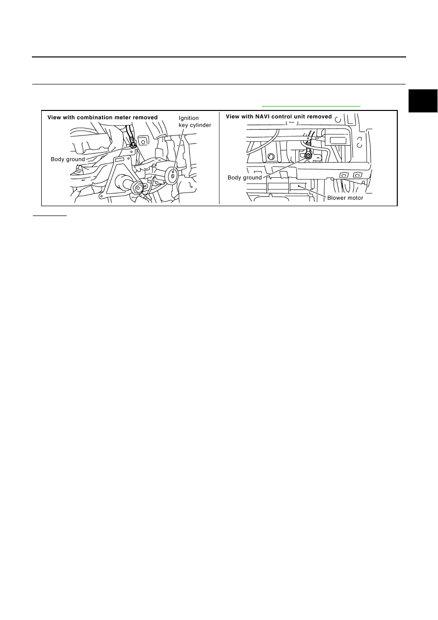
CHECK GROUND CONNECTIONS

1.

Turn ignition switch OFF.

2.

Loosen and retighten two ground screws on the body. Refer to 

EC-159, "Ground Inspection"

 .

OK or NG

OK

>> GO TO 2.

NG

>> Repair or replace ground connections.

PBIB2192E

EC-546

DTC P1564 ASCD STEERING SWITCH

2. 

CHECK ASCD STEERING SWITCH CIRCUIT

 With CONSULT-II

1.

Turn ignition switch ON.

2.

Select “MAIN SW”, “RESUME/ACC SW”, “SET SW” and “CANCEL SW” in “DATA MONITOR” mode with
CONSULT-II.

3.

Check each item indication under the following conditions.

 Without CONSULT-II

1.

Turn ignition switch ON.

2.

Check voltage between ECM terminal 99 and ground with press-
ing each button.

OK or NG

OK

>> GO TO 8.

NG

>> GO TO 3.

3. 

CHECK ASCD STEERING SWITCH GROUND CIRCUIT FOR OPEN AND SHORT

1.

Turn ignition switch OFF.

2.

Disconnect ECM harness connector.

3.

Disconnect combination switch harness connector M203.

4.

Check harness continuity between combination switch terminal 15 and ECM terminal 67.
Refer to Wiring Diagram.

5.

Also check harness for short to ground and short to power.

OK or NG

OK

>> GO TO 5.

NG

>> GO TO 4.

Switch Monitor 

item

Condition

Indication

MAIN switch

MAIN SW

Pressed

ON

Released

OFF

CANCEL switch

CANCEL SW

Pressed

ON

Released

OFF

RESUME/ACCEL-
ERATE switch

RESUME/ACC SW

Pressed

ON

Released

OFF

SET/COAST switch

SET SW

Pressed

ON

Released

OFF

SEC006D

Switch

Condition

Voltage [V]

MAIN switch

Pressed

Approx. 0

Released

Approx. 4

CANCEL switch

Pressed

Approx. 1

Released

Approx. 4

RESUME/ACCELERATE 
switch

Pressed

Approx. 3

Released

Approx. 4

SET/COAST switch

Pressed

Approx. 2

Released

Approx. 4

PBIB0311E

Continuity should exist.

DTC P1564 ASCD STEERING SWITCH

EC-547

C

D

E

F

G

H

I

J

K

L

M

A

EC

4. 

DETECT MALFUNCTIONING PART

Check the following.

Harness connectors M72, F102

Combination switch (spiral cable)

Harness for open and short between ECM and combination switch

>> Repair open circuit or short to ground or short to power in harness or connectors.

5. 

CHECK ASCD STEERING SWITCH INPUT SIGNAL CIRCUIT FOR OPEN AND SHORT

1.

Check harness continuity between ECM terminal 99 and combination switch terminal 14.
Refer to Wiring Diagram.

2.

Also check harness for short to ground and short to power.

OK or NG

OK

>> GO TO 7.

NG

>> GO TO 6.

6. 

DETECT MALFUNCTIONING PART

Check the following.

Harness connectors M72, F102

Combination switch (spiral cable)

Harness for open and short between ECM and combination switch

>> Repair open circuit or short to ground or short to power in harness or connectors.

7. 

CHECK ASCD STEERING SWITCH

Refer to 

EC-548, "Component Inspection"

 .

OK or NG

OK

>> GO TO 8.

NG

>> Replace steering wheel.

8. 

CHECK INTERMITTENT INCIDENT

Refer to 

EC-151, "TROUBLE DIAGNOSIS FOR INTERMITTENT INCIDENT"

 .

>> INSPECTION END

Continuity should exist.

EC-548

DTC P1564 ASCD STEERING SWITCH

Component Inspection

NBS000ZW

ASCD STEERING SWITCH

1.

Disconnect combination switch (spiral cable) harness connector M203.

2.

Check continuity between combination switch (spiral cable) ter-
minals 14 and 15 with pushing each switch.

If NG replace ASCD steering switch.

Switch

Condition

Resistance [

]

MAIN switch

Pressed

Approx. 0

Released

Approx. 4,000

CANCEL switch

Pressed

Approx. 250

Released

Approx. 4,000

RESUME/ACCELERATE 
switch

Pressed

Approx. 1,480

Released

Approx. 4,000

SET/COAST switch

Pressed

Approx. 660

Released

Approx. 4,000

PBIB2549E


Content   ..  414  415  416  417   ..