Infiniti G35 (V35). Manual - part 400
DTC P0500 VSS
EC-481
C
D
E
F
G
H
I
J
K
L
M
A
EC
5.
Maintain the following conditions for at least 60 consecutive sec-
onds.
6.
If 1st trip DTC is detected, go to
EC-482, "Diagnostic Procedure"
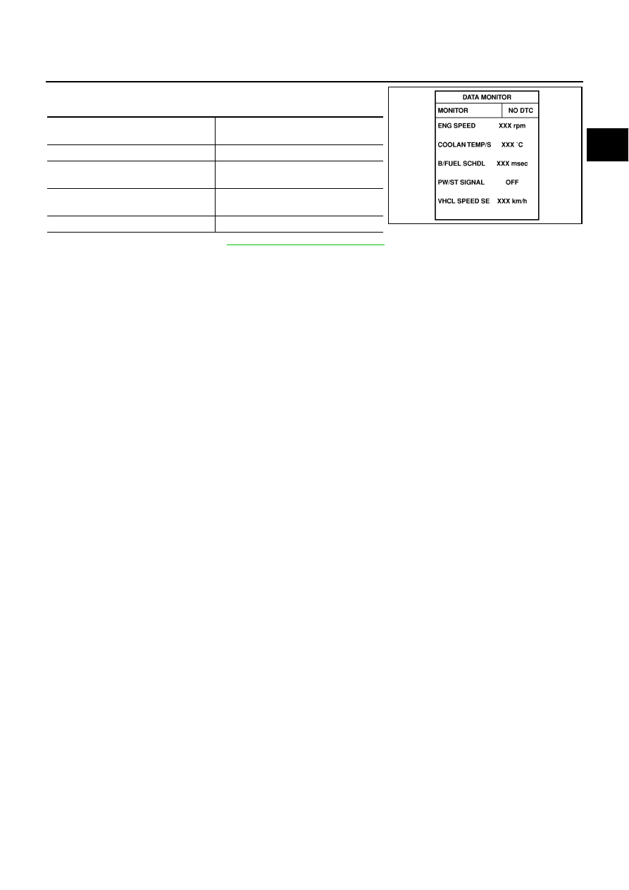
ENG SPEED
1,600 - 6,000 rpm (A/T)
1,800 - 6,000 rpm (M/T)
COOLAN TEMP/S
More than 70
°
C (158
°
F)
B/FUEL SCHDL
5.3 - 31.8 msec (A/T)
5.0 - 31.8 msec (M/T)
Shift lever
Except P or N position (A/T)
Except Neutral position (M/T)
PW/ST SIGNAL
OFF
SEF196Y