Infiniti G35 (V35). Manual - part 248


  Index      Infiniti     Infiniti G35 (V35) Coupe - service repair manual 2007 year


Search            


Content   ..  246  247  248  249   ..


Infiniti G35 (V35). Manual - part 248


TROUBLE DIAGNOSIS FOR SYSTEM

BRC-53

[VDC/TCS/ABS]

C

D

E

G

H

I

J

K

L

M

A

B

BRC

VDC/TCS/ABS ACTUATOR
Actuator Operation Inspection

1.

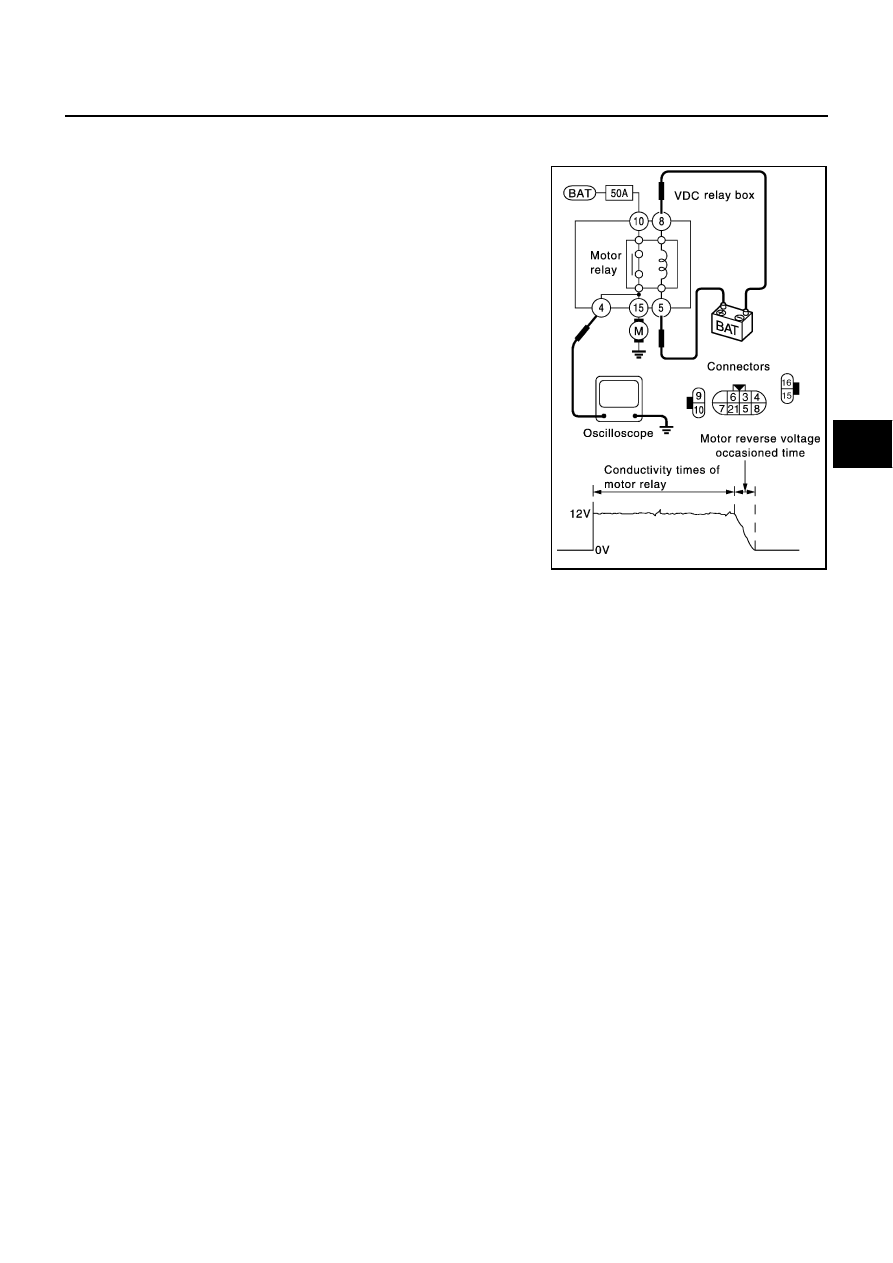
Turn ignition switch OFF, apply a voltage of 12 V between VDC
relay box connector E47 terminal 5 and 8, use an oscilloscope
to measure motor voltage at this time (between terminal 4 and
ground), and check motor reverse voltage occurrence time
when operation is stopped.

CAUTION:

Above check should be performed after motor relay unit
inspection to make sure relay operates normally.

To prevent overheating, do not drive actuator motor more
than 4 seconds.

Motor reverse voltage occurrence time is standard when
battery voltage is 12 V and the air temperature is 20

°

C

(68

°

F), and this time is a little shorter when battery voltage

is low or the air temperature is low.

Motor reverse voltage occurrence time:

0.1 second or more

SFIA0690E

BRC-54

[VDC/TCS/ABS]

TROUBLE DIAGNOSIS FOR SYMPTOMS

TROUBLE DIAGNOSIS FOR SYMPTOMS

PFP:00007

Excessive ABS Function Operation Frequency

NFS000KF

1. 

CHECK START

Check brake force distribution.

OK or NG

OK

>> GO TO 2.

NG

>> Check brake system

2. 

CHECK FRONT AND REAR AXLE

Make sure there is no excessive play in the front and rear axles.
OK or NG

OK

>> GO TO 3.

NG

>> Repair.

3. 

CHECK WHEEL SENSOR

Wheel Sensor Inspection

Wheel sensor mount and damage inspection

Sensor rotor mount and damage inspection

Wheel sensor connector connection inspection

Wheel sensor harness inspection

OK or NG

OK

>> GO TO 4.

NG

>>

Replace wheel sensor or sensor rotor.

Repair harness.

4. 

CHECK ABS WARNING LAMP DISPLAY

Make sure the warning lamp turns off approximately 1 sec. After the ignition switch is turned on or when driv-
ing.

OK or NG

OK

>> Normal

NG

>> Perform self-diagnosis. Refer to 

BRC-25, "Self-Diagnosis"

 .

Unexpected Pedal Reaction

NFS000KG

1. 

CHECK BRAKE PEDAL STROKE

Check brake pedal stroke.

Is the stroke too big?

YES

>>

Bleed air from the brake piping.

Check the brake pedal, brake booster, and master cylinder mount for play, looseness, and
brake system for fluid leaks, etc. If any malfunctions are found, make repair.

NO

>> GO TO 2.

2. 

CHECK FUNCTION

Disconnect the VDC/TCS/ABS control unit connector and make sure the braking force is sufficient when the
ABS in not operating. After the inspection, reconnect the connector. 
OK or NG

OK

>> GO TO 3. CHECK WHEEL SENSOR. Refer to 

BRC-54, "Excessive ABS Function Operation Fre-

quency"

 .

NG

>> Check brake system.

TROUBLE DIAGNOSIS FOR SYMPTOMS

BRC-55

[VDC/TCS/ABS]

C

D

E

G

H

I

J

K

L

M

A

B

BRC

The Braking Distance Is Long

NFS000KH

CAUTION:

On slippery road surfaces, the stopping distance might be longer with the ABS operating than when
the ABS is not operating.

1. 

CHECK FUNCTION

Disconnect VDC/TCS/ABS control unit connector to deactivate ABS. In this condition, check stopping dis-
tance. After inspection, connect connector.

OK or NG

OK

>> GO TO 3. CHECK WHEEL SENSOR. Refer to 

BRC-54, "Excessive ABS Function Operation Fre-

quency"

 .

NG

>>

Bleed air from the brake piping.

Check brake system.

The ABS Function Does Not Operate

NFS000KI

CAUTION:

The ABS does not operate when the speed is 10 km/h (6 MPH) or less.

1. 

CHECK ABS WARNING LAMP DISPLAY

Make sure the warning lamp turns off approximately 1 second after the ignition switch is turned on or when
driving.

OK or NG

OK

>> GO TO 3. CHECK WHEEL SENSOR. Refer to 

BRC-54, "Excessive ABS Function Operation Fre-

quency"

 .

NG

>> Perform self-diagnosis. Refer to 

BRC-25, "CONSULT-II Functions (ABS)"

 . 

Pedal Vibration or ABS Operation Sound Occurs

NFS000KJ

CAUTION:

Under the following conditions, when brake pedal is lightly depressed (just place a foot on it), ABS is
activated and vibration is felt. However, this is normal.

When shifting gears

When driving on slippery road

During cornering at high speed

When passing over bumps or grooves [50 mm (1.97 in) or more]

When pulling away just after starting engine (at approximately 10 km/h (6MPH) or higher)

1. 

SYMPTOM CHECK 1

Check if pedal vibration or operation sound occurs when the engine is started.

OK or NG

OK

>> GO TO 2.

NG

>> Perform self-diagnosis. Refer to 

BRC-25, "Self-Diagnosis"

 .

2. 

SYMPTOM CHECK 2

Check symptom when electrical component (headlamps, etc.) Switches are operated.
Does the symptom occur when the electrical component (head lamp, etc.) Switches are operated?

YES

>> Check if there is a radio, antenna, antenna lead wire, or wiring close to the control unit (or its wir-

ing), and if there is, move it farther away.

NO

>> GO TO 3. CHECK WHEEL SENSOR. Refer to 

BRC-54, "Excessive ABS Function Operation Fre-

quency"

 .

BRC-56

[VDC/TCS/ABS]

TROUBLE DIAGNOSIS FOR SYMPTOMS

Vehicle Jerks During VDC/TCS/ABS Control

NFS000KK

1. 

CHECK ENGINE SPEED SIGNAL

Conduct CONSULT-II VDC/TCS/ABS control unit “DATA MONITOR”.
Is engine speed at idle 400 rpm or higher?

YES

>> GO TO 3.

NO

>> GO TO 2.

2. 

CHECK ECM SELF-DIAGNOSIS RESULT ITEM

Perform ECM self-diagnosis.

Are self-diagnosis items displayed?

YES

>> Check the corresponding items. Refer to 

EC-83, "TROUBLE DIAGNOSIS"

  in “Engine Control

(EC section)”.

NO

>> GO TO 3.

3. 

SYMPTOM CHECK 1

Check if the vehicle jerks during VDC/TCS/ABS control.

OK or NG

OK

>> INSPECTION END

NG

>> GO TO 4.

4. 

CHECK A/T SELF-DIAGNOSIS RESULTS ITEM

Perform A/T self-diagnosis.

OK or NG

OK

>> GO TO 5.

NG

>> Check the corresponding items. Refer to 

AT-41, "TROUBLE DIAGNOSIS"

  in “A/T”.

5. 

SYMPTOM CHECK 2

Check if the vehicle jerks during VDC/TCS/ABS control.

OK or NG

OK

>> INSPECTION END

NG

>> GO TO 6.

6. 

CHECK SELF-DIAGNOSIS RESULT ITEM 1

Conduct self-diagnosis of the VDC/TCS/ABS control unit.

Are self-diagnosis items displayed?

YES

>> Check the corresponding items, make repairs, and re-conduct the VDC/TCS/ABS control unit self-

diagnosis.

NO

>> GO TO 7.

7. 

CHECK CONNECTOR

1.

Disconnect the VDC/TCS/ABS control unit and the ECM connectors, check the terminals for deformation,
disconnection, looseness, and so on. If there is an error, repair or replace the connector.

2.

Securely reconnect the connector and conduct self-diagnosis.

OK or NG

OK

>> If the connector terminal contact is loose, damaged, open or shorted, repair or replace the con-

nector terminal.

NG

>> GO TO 8.


Content   ..  246  247  248  249   ..