Infiniti G35 (V35). Manual - part 192
INTELLIGENT KEY SYSTEM
BL-155
C
D
E
F
G
H
J
K
L
M
A
B
BL
Check “KEY” Warning Lamp (GREEN)
NIS001KE
1.
CHECK WARNING LAMP OPERATION
With CONSULT-II
●
Check “INDICATOR” in “ACTIVE TEST” mode with CONSULT-
II.
●
Select “BLUE ON”.
“KEY”warning lamp (green) should illuminate.
Without CONSULT-II
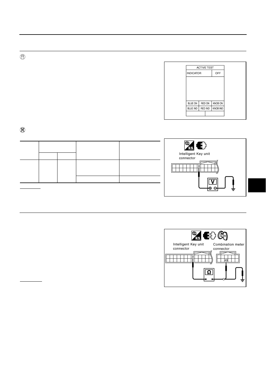
Check voltage between Intelligent Key unit harness connector M75 terminal 8 and ground.
OK or NG
OK
>> INSPECTION END
NG
>> GO TO 2.
2.
CHECK COMBINATION METER CIRCUIT
1.
Turn ignition switch OFF.
2.
Disconnect Intelligent Key unit connector and combination meter connector.
3.
Check continuity Intelligent Key unit harness connector M75 ter-
minal 8 and combination meter harness connector M20 terminal
49.
4.
Check continuity Intelligent Key unit harness connector M75 ter-
minal 8 and ground.
OK or NG
OK
>> GO TO 3.
NG
>> Repair or replace harness between Intelligent Key unit
and combination meter.
PIIB4356E
Connec-
tor
Terminal
(Wire cooler)
Condition
Voltage (V)
(Approx.)
(+)
(-)
M75
8 (R/L)
Ground
When Intelligent Key is
inside vehicle, press
ignition switch.
0
Ignition switch OFF
Battery voltage
PIIB4383E
8 (R/L) - 49 (R/L)
: Continuity should exist.
8 (R/L) - Ground
: Continuity should not exist.
PIIB4384E