Infiniti G35 (V35). Manual - part 129


  Index      Infiniti     Infiniti G35 (V35) Coupe - service repair manual 2007 year


Search            


Content   ..  127  128  129  130   ..


Infiniti G35 (V35). Manual - part 129


AUDIO

AV-31

C

D

E

F

G

H

I

J

L

M

A

B

AV

3. 

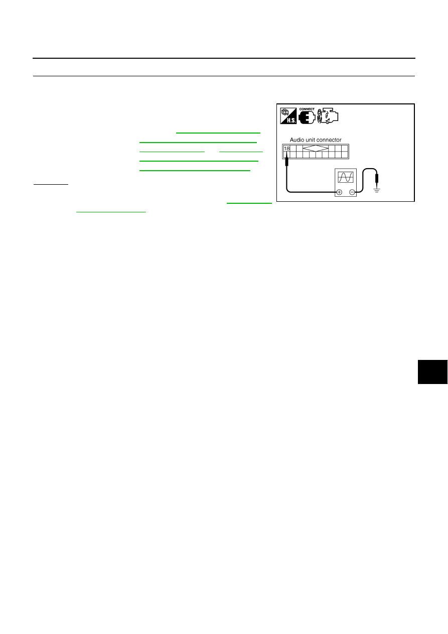
CHECK VEHICLE SPEED SIGNAL 

1.

Connect audio unit connector and combination meter connector.

2.

Start engine and drive vehicle at more than 40 km/h (25 MPH).

3.

Check the signal between audio unit harness connector M39
terminal 18 and ground with CONSULT-ll or oscilloscope.

OK or NG

OK

>> Replace audio unit.

NG

>> Check combination meter system. Refer to 

DI-13, "PRE-

LIMINARY CHECK"

  in “COMBINATION METERS”.

18 – Ground

: Refer to 

AV-21, "Terminals and 

Reference Value for Audio Unit 
for Base System"

  or 

AV-22, "Ter-

minals and Reference Value for 
Audio Unit for BOSE System"

 .

PKIB3844E

AV-32

AUDIO

Removal and Installation for Audio Unit 

NKS002HO

REMOVAL

1.

Remove cluster lid C. Refer to 

IP-10, "INSTRUMENT PANEL ASSEMBLY"

 .

2.

Unlock FPC (Flexible Print Circuit) connector lock on A/C and
audio controller side.

3.

Pull off flexible print circuit from connector.

4.

Remove screws (8). Remove audio unit and display unit assem-
bly (with navigation system) from cluster lid C.

5.

Separate audio unit from display unit assembly (with navigation
system).

6.

Remove 8 screws, and then bracket.

CAUTION:

Be careful not to allow foreign material to drop into CD
slot.

INSTALLATION

Installation is the reverse order of removal.

PKIB3960E

PKIB3961E

PKIB3962E

SKIA0938E

AUDIO

AV-33

C

D

E

F

G

H

I

J

L

M

A

B

AV

Removal and Installation for A/C and Audio Controller

NKS002HP

REMOVAL

1.

Remove audio unit and display unit assembly (with navigation
system) from cluster lid C. Refer to 

AV-32, "Removal and Instal-

lation for Audio Unit"

 .

2.

Remove NAVI switch (with navigation system). Refer to 

AV-91,

"Removal and Installation of NAVI Switch"

 .

3.

Remove screws (5) and remove A/C and audio controller.

INSTALLATION

Installation is the reverse order of removal.

Removal and Installation of Door Speaker 

NKS002HQ

REMOVAL

1.

Remove door finisher. Refer to 

EI-29, "DOOR FINISHER"

 .

2.

Remove bolts (3), and remove speaker.

INSTALLATION

Installation is the reverse order of removal.

Removal and Installation of Tweeter Behind Door Mirror

NKS002HR

REMOVAL

1.

Remove corner cover inner. Refer to 

EI-29, "DOOR FINISHER"

 .

2.

Remove screws (2), and remove tweeter behind door mirror.

INSTALLATION

Installation is the reverse order of removal.

Removal and Installation of Rear Side Speaker

NKS002HS

REMOVAL

1.

Remove rear side finisher. Refer to 

EI-31, "BODY SIDE TRIM"

 .

PKIB3963E

SKIA4535E

PKIA1772E

AV-34

AUDIO

2.

Remove screws (3) and remove speaker.

INSTALLATION

Installation is the reverse order of removal.

Removal and Installation of Woofer

NKS002HT

REMOVAL

1.

Remove rear parcel shelf finisher. Refer to 

EI-33, "REAR PARCEL SHELF FINISHER"

 .

2.

Remove screws (4), and remove woofer.

INSTALLATION

Installation is the reverse order of removal.

Removal and Installation of BOSE Speaker Amp.

NKS002HU

REMOVAL

1.

Remove luggage floor carpet and spare tire cover. Refer to 

EI-38, "Removal and Installation for Trunk

Room Trim"

 .

2.

Remove trunk side box. Refer to 

EI-38, "Removal and Installation for Trunk Room Trim"

 .

3.

Remove TEL adapter unit connectors and TEL antenna feeder clip. (With telephone system)  

4.

Remove nuts (3), and remove BOSE speaker amp. from trunk
room floor.

PKIA2373E

PKIA2374E

PKIA2375E


Content   ..  127  128  129  130   ..