Infiniti G35 (V35). Manual - part 100
TROUBLE DIAGNOSIS
ATC-71
C
D
E
F
G
H
I
K
L
M
A
B
ATC
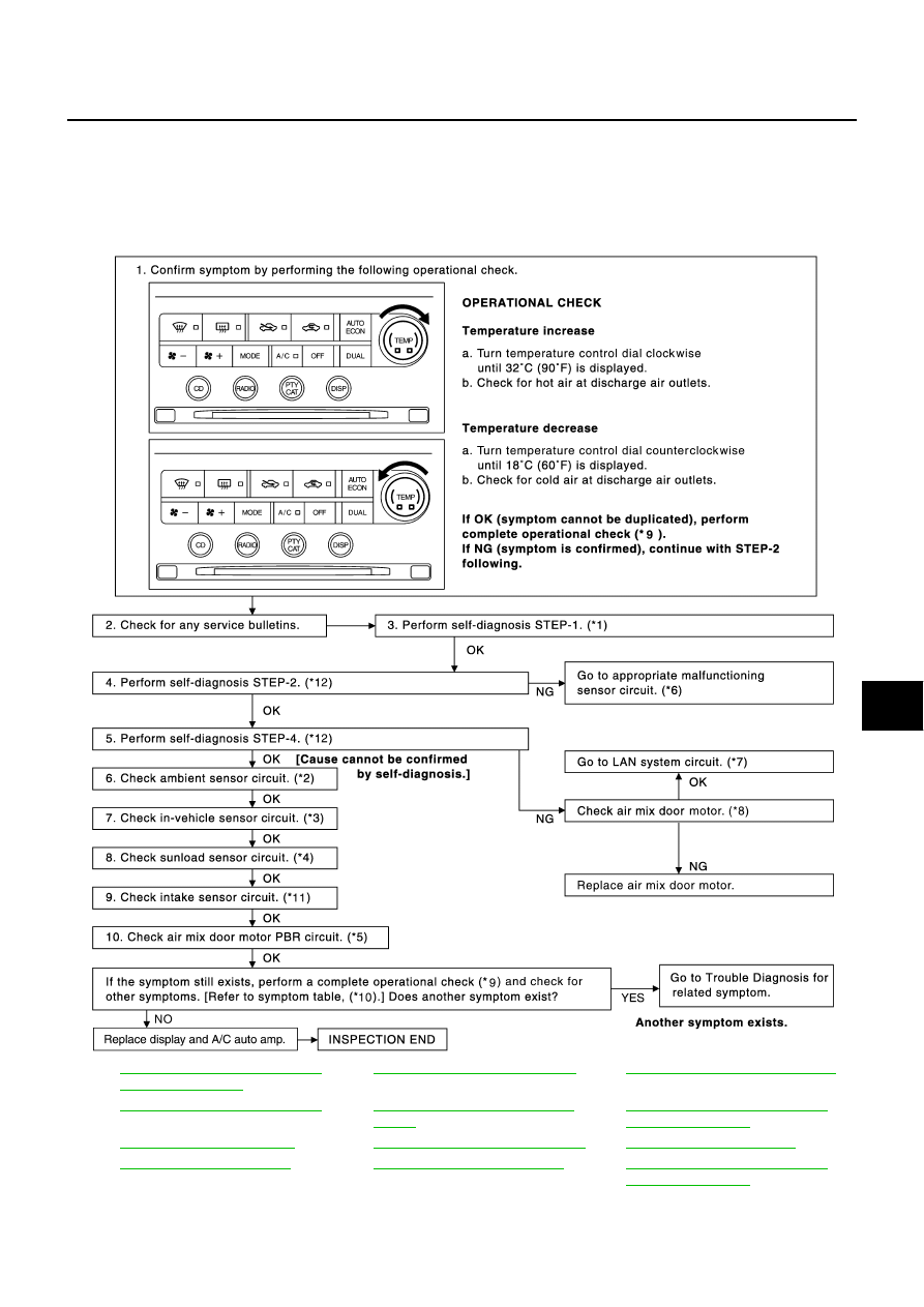
Air Mix Door Motor Circuit
NJS0003G
SYMPTOM
●
Discharge air temperature does not change.
●
Air mix door motor does not operate normally.
INSPECTION FLOW
*1
ATC-52, "FUNCTION CONFIRMA-
TION PROCEDURE"
, see No. 1.
*2
ATC-100, "Ambient Sensor Circuit"
*3
ATC-103, "In-vehicle Sensor Circuit"
*4
ATC-106, "Sunload Sensor Circuit"
*5
ATC-73, "Air Mix Door Motor PBR
Circuit"
*6
ATC-52, "FUNCTION CONFIRMA-
TION PROCEDURE"
, see No. 14.
*7
*8
ATC-71, "Air Mix Door Motor Circuit"
*9
*10
*11
ATC-109, "Intake Sensor Circuit"
*12
ATC-52, "FUNCTION CONFIRMA-
TION PROCEDURE"
, see No. 5 to
7.
RJIA3505E