Infiniti G35 (V35). Manual - part 29


  Index      Infiniti     Infiniti G35 (V35) Coupe - service repair manual 2007 year


Search            


Content   ..  27  28  29  30   ..


Infiniti G35 (V35). Manual - part 29


DTC P0705 PARK/NEUTRAL POSITION SWITCH

AT-107

D

E

F

G

H

I

J

K

L

M

A

B

AT

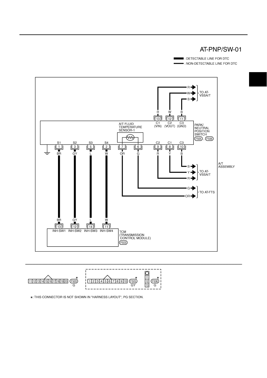
Wiring Diagram — AT — PNP/SW

NCS000CV

TCWM0248E

AT-108

DTC P0705 PARK/NEUTRAL POSITION SWITCH

Diagnostic Procedure

NCS000CW

1. 

CHECK PNP SW CIRCUIT

 With CONSULT-II

1.

Turn ignition switch ON.

2.

Select “SELECTION FROM MENU” in “DATA MONITOR” mode
for “A/T” with CONSULT-II.

3.

Check if correct selector lever position (N/P, R or D) is displayed
as selector lever is moved into each position.

OK or NG

OK

>> GO TO 5.

NG

>> GO TO 2.

2. 

CHECK TCM POWER SUPPLY AND GROUND CIRCUIT

Check TCM power supply and ground circuit. Refer to 

AT-172, "MAIN POWER SUPPLY AND GROUND CIR-

CUIT"

 .

OK or NG

OK

>> GO TO 3.

NG

>> Repair or replace damaged parts.

3. 

DETECT MALFUNCTIONING ITEM

Check A/T assembly harness connector pin terminals for damage or loose connection with harness connector.

OK or NG

OK

>> GO TO 4.

NG

>> Repair or replace damaged parts.

Item name

Condition 

Display value

SLCT LVR POSI

Selector lever in “N” and “P” positions.

N/P

Selector lever in “R” position.

R

Selector lever in “D” position.

D

SCIA5296E

DTC P0705 PARK/NEUTRAL POSITION SWITCH

AT-109

D

E

F

G

H

I

J

K

L

M

A

B

AT

4. 

CHECK SUB-HARNESS

1.

Remove control valve with TCM. Refer to 

AT-225, "Control Valve with TCM and A/T Fluid Temperature

Sensor 2"

 .

2.

Disconnect park/neutral position switch connector and TCM connector.

3.

Check continuity between park/neutral position switch connector
terminals and TCM connector terminals.

4.

If OK, check harness for short to ground and short to power.

5.

Reinstall any part removed.

OK or NG

OK

>> Replace control valve with TCM. Refer to 

AT-225, "Control Valve with TCM and A/T Fluid Temper-

ature Sensor 2"

 .

NG

>> Replace open circuit or short to ground and short to power in harness or connectors.

5. 

CHECK DTC

Perform 

AT-106, "DTC Confirmation Procedure"

 .

OK or NG

OK

>> INSPECTION END

NG

>> GO TO 2.

Item

 Connector

Terminal

Continuity

Park/neutral position switch 
connector

F505

1

Yes

TCM connector 

F503

13

Park/neutral position switch 
connector

F505

2

Yes

TCM connector 

F503

11

Park/neutral position switch 
connector

F505

3

Yes

TCM connector 

F503

12

Park/neutral position switch 
connector

F505

5

Yes

TCM connector 

F503

14

SCIA5457E

AT-110

DTC P0717 TURBINE REVOLUTION SENSOR

DTC P0717 TURBINE REVOLUTION SENSOR

PFP:31935

Description

NCS000EG

The turbine revolution sensor detects input shaft rpm (revolutions per minute). It is located on the input side of
the A/T. Monitors revolution of sensor 1 and sensor 2 for non-standard conditions.

CONSULT-II Reference Value

NCS000EH

On Board Diagnosis Logic

NCS000EI

This is an OBD-II self-diagnostic item.

Diagnostic trouble code “P0717 TURBINE REV S/CIRC” with CONSULT-II or 11th judgment flicker with-
out CONSULT-II is detected under the following conditions.

When TCM does not receive the proper voltage signal from the sensor.

When TCM detects an irregularity only at position of 4th gear for turbine revolution sensor 2.

Possible Cause

NCS000EJ

Harness or connectors.
(Sensor circuit is open or shorted.)

Turbine revolution sensor 1 and/or 2.

DTC Confirmation Procedure

NCS000EK

CAUTION:

Always drive vehicle at a safe speed.

Be careful not to rev engine into the red zone on the tachometer.

NOTE:
If “DTC Confirmation Procedure” has been previously performed, always turn ignition switch OFF and
wait at least 10 seconds before performing the next test.
After the repair, perform the following procedure to confirm the malfunction is eliminated.

 WITH CONSULT-II

1.

Turn ignition switch ON.

2.

Select “SELECTION FROM MENU” in “DATA MONITOR” mode
for “A/T” with CONSULT-II and check monitor “VHCL/S SE-A/T”,
“ACCELE POSI”, “ENGINE SPEED”, “SLCT LVR POSI” and
“GEAR”.

3.

Touch “START”.

4.

Start engine and maintain the following conditions for at least 5
consecutive seconds.
VHCL/S SE-A/T: 40 km/h (25 MPH) or more
ACCELE POSI: More than 0.5/8
ENGINE SPEED: 1,500 rpm or more
SLCT LVR POSI: “D” position 
GEAR (Turbine revolution sensor 1): “4” or “5” position
GEAR (Turbine revolution sensor 2): All positions
Driving location: Driving the vehicle uphill (increased engine load) will help maintain the driving
conditions required for this test.

5.

If DTC is detected, go to 

AT-111, "Diagnostic Procedure"

 .

 WITH GST

Follow the procedure “WITH CONSULT-II”.

Item name

Condition 

Display value

TURBINE REV

 During driving (lock-up ON)

 Approximately matches the engine speed.

BCIA0031E


Content   ..  27  28  29  30   ..