Content .. 1093 1094 1095 1096 ..
Infiniti EX35. Manual - part 1095
MWI-58
< COMPONENT DIAGNOSIS >
FUEL LEVEL SENSOR SIGNAL CIRCUIT
4.
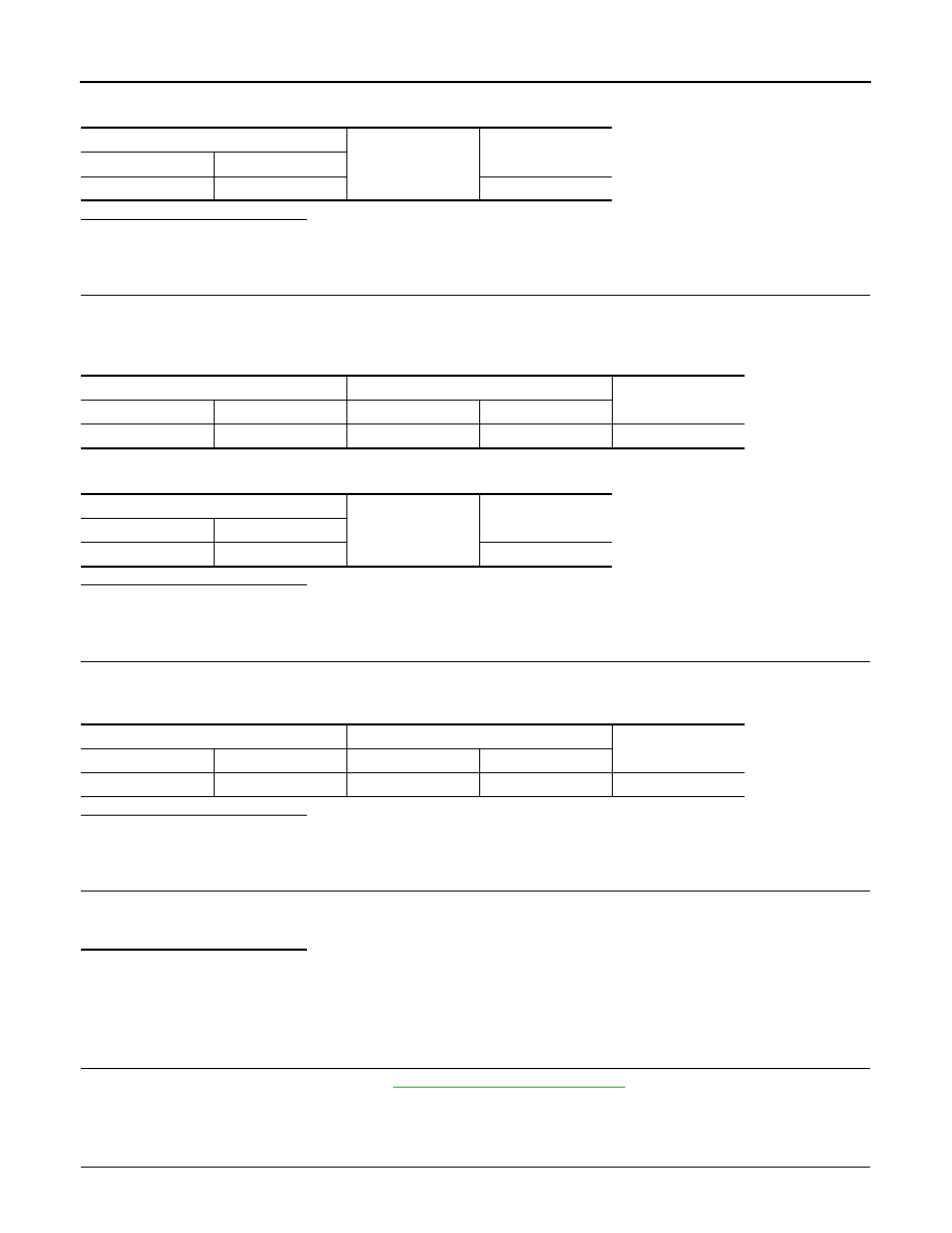
Check continuity between unified meter and A/C amp. harness connector and ground.
Is the inspection result normal?
YES
>> GO TO 3.
NO
>> Repair harness or connector.
3.
CHECK FUEL LEVEL SENSOR (MAIN-SUB) CIRCUIT
1.
Disconnect fuel level sensor unit and fuel pump (main) connector.
2.
Check continuity between fuel level sensor unit (sub) harness connector and fuel level sensor unit and
fuel pump (main) harness connector.
3.
Check continuity between fuel level sensor unit (sub) harness connector and ground.
Is the inspection result normal?
YES
>> GO TO 4.
NO
>> Repair harness or connector.
4.
CHECK FUEL LEVEL SENSOR (MAIN) CIRCUIT
Check continuity between fuel level sensor unit and fuel pump (main) harness connector and unified meter
and A/C amp. harness connector.
Is the inspection result normal?
YES
>> GO TO 5.
NO
>> Repair harness or connector.
5.
CHECK INSTALLATION CONDITION
Check fuel level sensor unit installation, and check whether the float arm interferes or binds with any of the
internal components in the fuel tank.
Is the inspection result normal?
YES
>> INSPECTION END
NO
>> Install the fuel level sensor unit properly.
Component Inspection
INFOID:0000000003140212
1.
REMOVE FUEL LEVEL SENSOR UNIT
Remove the fuel level sensor unit. Refer to
FL-5, "Removal and Installation"
.
>> GO TO 2.
2.
CHECK FUEL LEVEL SENSOR UNIT AND FUEL PUMP (MAIN)
Unified meter A/C amp.
Ground
Continuity
Connector
Terminal
M67
42
Not existed
Fuel level sensor unit (sub)
Fuel level sensor unit and fuel pump (main)
Continuity
Connector
Terminal
Connector
terminal
B21
2
B22
2
Existed
Fuel level sensor unit (sub)
Ground
Continuity
Connector
Terminal
B21
2
Not existed
Fuel level sensor unit and fuel pump (main)
Unified meter A/C amp.
Continuity
Connector
Terminal
Connector
terminal
B22
5
M67
58
Existed