Hummer H3. Manual - part 872


  Index      Hummer     Hummer H3 - service repair manual 2006-2009 year


Search            


Content   ..  870  871  872  873   ..


Hummer H3. Manual - part 872


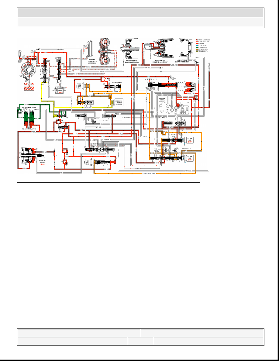
Fig. 491: Overdrive Range, Third Gear Hydraulic Circuit Diagram 
Courtesy of GENERAL MOTORS CORP. 

OVERDRIVE RANGE, FOURTH GEAR - TORQUE CONVERTER CLUTCH APPLIED 

At higher vehicle speeds, the Hydra-matic 4L60-E transmission uses an overdrive gear ratio 
(fourth gear) in order to increase fuel economy and in order to maximize engine performance. 
When vehicle operating conditions are appropriate, the PCM energizes the 1-2 shift solenoid 
valve to shift the transmission into fourth gear. 

1-2 Shift Solenoid (SS) Valve 

Energized (turned ON) by the PCM, the normally open solenoid closes and blocks signal A fluid 
from exhausting through the solenoid. This creates pressure in the signal A fluid circuit. 

2-3 Shift Solenoid (SS) Valve 

De-energized (OFF) as in third gear, the 2-3 shift solenoid valve exhausts signal B fluid through 
the solenoid. 

1-2 Shift Valve 

D432 fluid pressure from the 2-3 shift valve and spring force hold the valve in the upshift position 


2007 Hummer H3 

2007 TRANSMISSION Automatic Transmission - 4L60-E/4L65-E/4L70-E - H3


against signal A fluid pressure. 

3-4 Shift Valve 

Signal A fluid pressure moves the valve into the upshift position against the spring force. In this 
position, the valve routes 3-4 signal fluid into the 4th signal fluid circuit. 

3-4 Relay Valve and 4-3 Sequence Valve 

4th signal fluid pressure moves both valves into the upshift (fourth gear) position against the 
spring force acting on the 4-3 sequence valve. This causes the following changes: 


Orificed (#7) 2nd fluid is routed through the 3-4 relay valve and into the servo feed fluid 
circuit.  


Servo feed fluid is routed through the 4-3 sequence valve and into the 4th fluid circuit.  


3-4 accumulator fluid routed from the 2-3 shuttle valve is blocked by both valves.  

2-4 Servo Assembly 

4th fluid is routed through the center of the servo apply pin and acts on the apply side of the 4th 
apply piston. 4th fluid pressure moves the 4th apply piston against the apply pin spring force 
acting on the release side of the 4th apply piston. This action moves the apply pin and applies the 
2-4 band in order to obtain fourth gear. 

2-4 Band Apply Accumulation 

2-3 Shift Valve Train 

The valve train remains in the upshift position with the AFL fluid pressure acting on the 2-3 shift 
valve. In addition to its operation third gear, the 2-3 shift valve directs servo feed fluid into the 3-
4 accumulator fluid circuit. 

3-4 Accumulator Assembly 

3-4 accumulator fluid pressure moves the 3-4 accumulator piston against spring force and orificed 
accumulator fluid pressure. This action absorbs initial 4th clutch apply fluid pressure in order to 
cushion the 2-4 band apply. Remember that both of the 3-4 accumulator and 4th fluid circuits are 
fed by servo feed fluid. As 3-4 accumulator fluid fills the accumulator, any air in the system will 
exhaust through office #19. This piston movement forces some orificed accumulator fluid out of 
the 3-4 accumulator assembly. 

3-4 Accumulator Checkball (#1) 


2007 Hummer H3 

2007 TRANSMISSION Automatic Transmission - 4L60-E/4L65-E/4L70-E - H3


The accumulator fluid forced from the accumulator unseats the #1 checkball and enters the 
accumulator fluid circuit. This fluid is routed to the accumulator valve. This is shown by the 
arrow directions in the fluid circuit. 

Accumulator Valve 

Accumulator fluid forced from the 3-4 accumulator is orificed to the end of the accumulator 
valve. This fluid pressure, in addition to spring force and torque signal fluid pressure, regulates 
the exhaust of excess accumulator fluid pressure through the middle of the valve. This regulation 
helps control the 2-4 band apply feel. 

3-2 Control Solenoid Valve and 3-2 Control Valve 

The solenoid remains open and routes AFL fluid into the 3-2 signal fluid circuit. 3-2 signal fluid 
pressure holds the 3-2 control valve against spring force, thereby blocking the 3rd accumulator 
and 3-4 clutch fluid circuits. 

Torque Converter Clutch Applies 

TCC Solenoid Valve 

When operating conditions are appropriate, the PCM energizes the normally open TCC solenoid 
valve. This closes the solenoid, blocks the converter feed fluid from exhausting and creates 
pressure in the converter feed fluid circuit at the converter clutch apply valve and TCC solenoid 
valve. 

Converter Clutch Apply Valve 

Converter feed fluid pressure moves the valve against spring force and into the apply position. In 
this position, release fluid is open to an exhaust port and regulated apply fluid fills the apply fluid 
circuit. Converter feed fluid is routed through the converter clutch apply valve to feed the cooler 
fluid circuit. 

Torque Converter 

Release fluid from behind the pressure plate exhausts through the end of the turbine shaft. Apply 
fluid pressure is routed between the converter hub and stator shaft where it enters the torque 
converter. This fluid applies the converter clutch against the converter cover and keeps the 
converter filled with fluid. 

TCC Apply Checkball (#9) 

Release fluid, exhausting from the converter, seats the #9 checkball located in the end of the 


2007 Hummer H3 

2007 TRANSMISSION Automatic Transmission - 4L60-E/4L65-E/4L70-E - H3


turbine shaft and is orificed around the ball. Orificing the exhausting release fluid controls the 
converter clutch apply rate, along with the TCC PWM solenoid valve. 

TCC PWM Solenoid Valve 

The torque converter clutch pulse width modulation (TCC PWM) solenoid valve controls the 
regulated apply valve position. This is done through the use of pulse width modulation (duty 
cycle operation). The solenoid duty cycle is controlled by the PCM in relation to vehicle 
operating conditions and regulates actuator feed limit (AFL) fluid into the CC signal circuit, 
through the #9 orifice and to the isolator valve. This controls line pressure flow through the 
regulated apply valve, into the regulated apply circuit and provides a smooth engagement of the 
TCC. 

Fig. 492: Overdrive Range, Fourth Gear - TCC Applied Hydraulic Circuit Diagram 
Courtesy of GENERAL MOTORS CORP. 

OVERDRIVE RANGE, 4-3 DOWNSHIFT 

When the transmission is operating in fourth gear, a forced 4-3 downshift occurs if there is a 
significant increase in throttle position. At minimum throttle, the vehicle speed decreases 
gradually (coastdown) and the PCM commands a 4-3 downshift. The PCM also initiates a forced 
4-3 downshift when the throttle position remains constant but engine load is increased, such as 


2007 Hummer H3 

2007 TRANSMISSION Automatic Transmission - 4L60-E/4L65-E/4L70-E - H3


Content   ..  870  871  872  873   ..