Hummer H3. Manual - part 404


  Index      Hummer     Hummer H3 - service repair manual 2006-2009 year


Search            


Content   ..  402  403  404  405   ..


Hummer H3. Manual - part 404


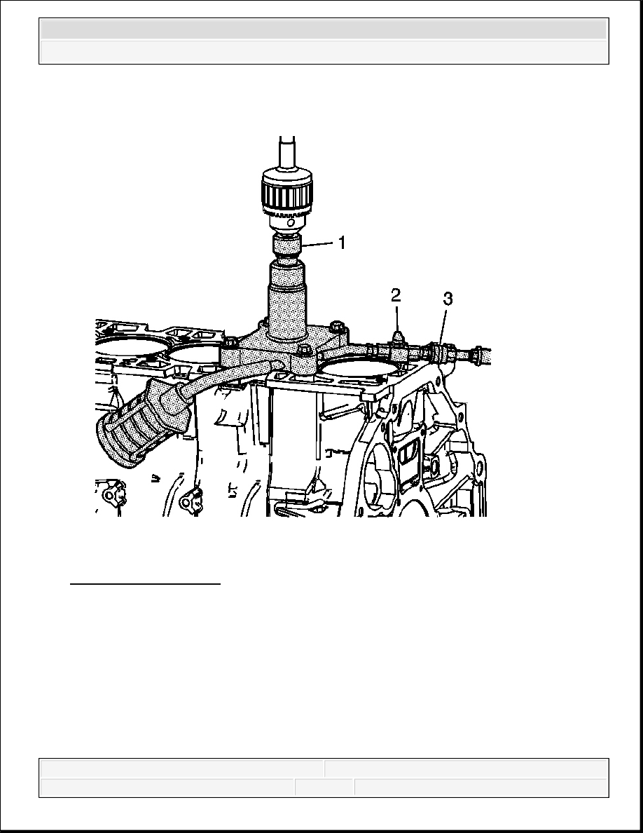
Fig. 448: Drive Adapter 
Courtesy of GENERAL MOTORS CORP. 

12. Fasten drive adapter EN 45680-866 (1) into the drill chuck. 

NOTE:

For proper tool operation, a drill motor with a 1/2 inch chuck, 1 
1/8 hp, 7 amps, triple gear reduction and a 450-600 RPM 
rotational speed in a clockwise direction must be used. If the 
proper drill motor is not used, damage to the cylinder bore 
sleeve will occur.


2007 Hummer H3 

2007 ENGINE Engine Mechanical - 3.7L - H3


13. Connect a compressed air supply (75-125 psi) to the male quick connect (3) located on trim 

tool assembly EN 45680-411. Turn the compressed air valve (2) to the open position. This 
starts the venturi vacuum system that will catch the metal shavings. 

14. Place drive adapter EN 45680-866 and drill assembly (1) vertically onto the drive adapter 

end of trim tool assembly EN 45680-411. Do not apply downward force on the drill until 
full rotational speed has been reached. After reaching full rotational speed, apply firm 
downward force until the cutting action is complete.  

15. Remove drive adapter EN 45680-866 (1) and drill assembly from the trim tool assembly 

EN 45680-411.  

16. Turn off the compressed air valve (2).  

17. Remove trim tool assembly EN 45680-411 from the engine block.  

18. Remove any material shavings that may be found on the metal shaving catch plug EN 

45680-413.  

19. Wipe the cylinder bore sleeve and surrounding areas free of any powder residue and then 

remove the metal shaving catch plug EN 45680-413. 

NOTE:

Ensure that there are no crimps in the air feed hose or the 
vacuum hose. Crimps in the hose may cause metal shavings to 
exit the cutting tool in any direction, causing engine damage.

IMPORTANT: It should not take longer than 15 seconds to complete the 

trimming procedure. If it does, the trimming bits must be 
repositioned to a new cutting surface.


2007 Hummer H3 

2007 ENGINE Engine Mechanical - 3.7L - H3


Fig. 449: Checking Cylinder Block Deck Surface With Straight Edge 
Courtesy of GENERAL MOTORS CORP. 

20. Install a straight edge on the cylinder block perpendicular to the crankshaft center line.  

21. Using a light, illuminate the backside of the straight edge. 


2007 Hummer H3 

2007 ENGINE Engine Mechanical - 3.7L - H3


Fig. 450: View Of Improperly Cut Cylinder Bore Sleeve 
Courtesy of GENERAL MOTORS CORP. 

22. Looking at the front of the straight edge, check to see if light is protruding through the 

bottom of the straight edge and the top of the cylinder bore sleeve flange. If light is present 
on either side or both sides of the cylinder bore sleeve, the cylinder bore sleeve is cut 
incorrectly and a new cylinder bore sleeve needs to be installed. 


2007 Hummer H3 

2007 ENGINE Engine Mechanical - 3.7L - H3


Content   ..  402  403  404  405   ..