Hummer H3. Manual - part 1626


  Index      Hummer     Hummer H3 - service repair manual 2006-2009 year


Search            


Content   ..  1624  1625  1626  1627   ..


Hummer H3. Manual - part 1626


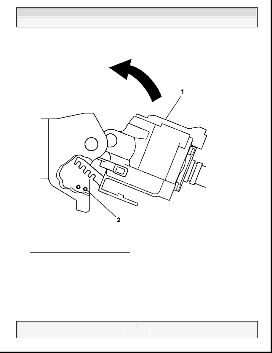
Fig. 41: Locking Shoes To Dowel Pins 
Courtesy of GENERAL MOTORS CORP. 

2. Using the tilt lever, position the lock shoes to the dowel pins (2).  

3. Rotate the steering column tilt head housing (1) in order to align the holes for the steering 

column pivot pins. 


2007 Hummer H3 

2007 STEERING Steering Wheel and Column - H3


Fig. 42: View Of Pivot Pins At Steering Column Assembly 
Courtesy of GENERAL MOTORS CORP. 

4. Install the new steering column pivot pins by performing the following steps: 

1. Lubricate the steering column pivot pins (1) with, GM P/N 12346293 (Canadian P/N 

992723).  

2. Press the steering column pivot pins (1) until the they are firmly seated.  

3. Stake the steering column pivot pins (1) at 3 locations each.  

5. Install the tilt spring. Refer to Steering Column Tilt Spring Replacement.  

6. Install the ignition lock cylinder case. Refer to Ignition Lock Cylinder Case 

Replacement .  

7. Install the steering column. Refer to Steering Column Replacement.  

STEERING SHAFT UPPER BEARING REPLACEMENT 

Removal Procedure 

1. Remove the steering column tilt head housing. Refer to Steering Column Tilt Head 

Housing Replacement.  


2007 Hummer H3 

2007 STEERING Steering Wheel and Column - H3


2. Remove the steering shaft upper bearing from the steering column tilt head housing.  

Installation Procedure 

1. Install the steering shaft upper bearing into the steering column tilt head housing.  

2. Install the steering column tilt head housing. Refer to Steering Column Tilt Head 

Housing Replacement.  

STEERING COLUMN REPLACEMENT 

Tools Required 

J 42640 Steering Column Anti-Rotation Pin 

Removal Procedure 

1. Disable the supplemental inflatable restraint (SIR) System. Refer to SIR Disabling and 

Enabling . 

CAUTION: Refer to SIR Caution .

NOTE:

Once the steering column is removed from the vehicle, the 
column is extremely susceptible to damage. Dropping the 
column assembly on the end could collapse the steering shaft 
or loosen the plastic injections, which maintain column 
rigidity. Leaning on the column assembly could cause the 
jacket to bend or deform. Any of the above damage could 
impair the columns collapsible design. Do NOT hammer on the 
end of the shaft, because hammering could loosen the plastic 
injections, which maintain column rigidity. If you need to 
remove the steering wheel, refer to Steering Wheel 
Replacement procedure in this section.

NOTE:

The front wheels of the vehicle must be maintained in the 
straight ahead position and the steering column must be in the 
LOCK position before disconnecting the steering column or 
intermediate shaft. Failure to follow these procedures will 
cause improper alignment of some components during 
installation and result in damage to the SIR coil assembly.


2007 Hummer H3 

2007 STEERING Steering Wheel and Column - H3


Fig. 43: Steering Wheel Lock Tool 
Courtesy of GENERAL MOTORS CORP. 

2. Lock the steering column through the access hole in the lower steering column trim cover 

using anti-rotation pin J 42640 .  

3. Remove the driver knee bolster bracket. Refer to Driver Knee Bolster Bracket 

Replacement (Left Hand Drive) or Driver Knee Bolster Bracket Replacement (Right 
Hand Drive)
 .  

4. Remove the upper intermediate steering shaft bolt at the steering column. Refer to Upper 

Intermediate Steering Shaft Replacement.  

5. Disconnect any electrical connectors as needed. 


2007 Hummer H3 

2007 STEERING Steering Wheel and Column - H3


Content   ..  1624  1625  1626  1627   ..