Content .. 1094 1095 1096 1097 ..
Hummer H3. Manual - part 1096
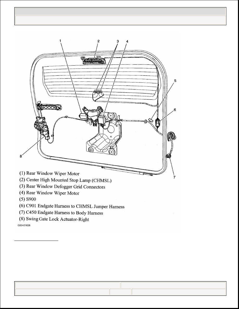
Fig. 56: Endgate
Courtesy of GENERAL MOTORS CORP.
2006 Hummer H3
2006 GENERAL MOTORS H3
|
|
|
Content .. 1094 1095 1096 1097 ..
Fig. 56: Endgate
2006 Hummer H3 2006 GENERAL MOTORS H3
|