Hummer H2. Manual - part 64


  Index      Hummer     Hummer H2 - service repair manual 2004 year


Search            


Content   ..  62  63  64  65   ..


Hummer H2. Manual - part 64


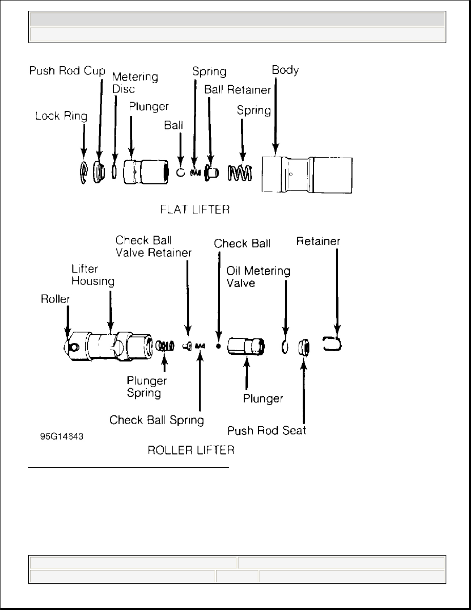
Fig. 13: Typical Hydraulic Valve Lifter Assemblies 

Mechanical Lifters 

Lifter assemblies must be installed in original locations. Remove rocker arm assembly and push rod. Mark 
components for location. Some applications require intake manifold or lifter cover removal. Remove lifter 
retainer plate (if used). To remove lifters, use lifter remover or magnet.  

Inspect push rod contact area and lifter body for scoring or signs of wear. If body is scored, inspect lifter bore 


1998 Chevrolet Pickup C1500 

GENERAL INFORMATION Engine Overhaul Procedures


for damage and lack of lubrication. Note amount of wear in lifter body-to-camshaft contact area. Surface must 
have smooth and convex contact face. If wear is apparent, carefully inspect cam lobe.  

Coat lifter base, roller (if equipped) and lifter body with ample amount of Molykote or camshaft lubricant. 
Install lifter in original location. Install remaining components. Tighten bolts to specification. Adjust valves. 
See VALVE ADJUSTMENT .  

PISTONS, CONNECTING RODS & BEARINGS 

RIDGE REMOVAL 

Ridge in cylinder wall must be removed prior to piston removal. Failure to remove ridge prior to removing 
pistons will cause piston damage in piston ring lands or grooves.  

With piston at bottom dead center, place rag in bore to trap metal chips. Install ridge reamer in cylinder bore. 
Adjust ridge reamer using manufacturer's instructions. Remove ridge using ridge reamer. DO NOT remove an 
excessive amount of material. Ensure ridge is completely removed.  

PISTON & CONNECTING ROD REMOVAL 

Note top of piston. Some pistons may contain a notch, arrow or be marked FRONT. Piston must be installed in 
proper direction to prevent damage with valve operation.  

Check that connecting rod and cap are numbered for cylinder location and which side of cylinder block the 
number faces. Proper cap and connecting rod must be installed together. Connecting rod cap must be installed 
on connecting rod in proper direction to ensure bearing lock procedure. Mark connecting rod and cap if 
necessary. Pistons must be installed in original location.  

Remove cap retaining nuts or bolts. Remove bearing cap. Install tubing protectors on connecting rod bolts. This 
protects cylinder walls from scoring during removal. Ensure proper removal of ridge. Push piston and 
connecting rod from cylinder. Connecting rod boss can be tapped with a wooden dowel or hammer handle to 
aid in removal.  

PISTON & CONNECTING ROD 

Disassembly 

Using ring expander, remove piston rings. Remove piston pin retaining rings (if equipped). Note direction of 
piston installation on connecting rod. On pressed type piston pins, special fixtures and procedures according to 
manufacturer must be used to remove piston pins. Follow manufacturer's recommendations to avoid piston 
distortion or breakage.  

Cleaning 

Remove all carbon and varnish from piston. Pistons and connecting rods may be cleaned in cold type chemical 
tank. Using ring groove cleaner, clean all deposits from ring grooves. Ensure all deposits are cleaned from ring 
grooves to prevent ring breakage or sticking. DO NOT attempt to clean pistons with wire brush. 


1998 Chevrolet Pickup C1500 

GENERAL INFORMATION Engine Overhaul Procedures


Inspection 

Inspect pistons for nicks, scoring, cracks or damage in ring areas. Connecting rod should be checked for cracks 
using Magnaflux procedure. Piston diameter must be measured in manufacturer's specified area.  

Using telescopic gauge and micrometer, measure piston pin bore of piston in 2 areas, 90 degrees apart. This is 
done to check diameter and out-of-round.  

Install proper bearing cap on connecting rod. Ensure bearing cap is installed in proper location. Tighten bolts or 
nuts to specification. Using inside micrometer, measure inside diameter in 2 areas, 90 degrees apart.  

Connecting rod I.D. and out-of-round must be within specification. Measure piston pin bore I.D. and piston pin 
O.D. All components must be within specification. Subtract piston pin diameter from piston pin bore in piston 
and connecting rod to determine proper fit.  

Connecting rod length must be measured from center of crankshaft journal inside diameter to center of piston 
pin bushing using proper caliper. Connecting rods must be the same length. Connecting rods should be checked 
on an alignment fixture for bent or twisted condition. Replace all components which are damaged or not within 
specification.  

PISTON & CYLINDER BORE FIT 

Ensure cylinder is checked for taper, out-of-round and properly honed prior to checking piston and cylinder 
bore fit. See CYLINDER BLOCK . Using dial bore gauge, measure cylinder bore.  

Measure piston skirt diameter at 90 degree angle to piston pin at specified area by manufacturer. Subtract piston 
diameter from cylinder bore diameter to determine piston-to-cylinder clearance. Clearance must be within 
specification. Mark piston for proper cylinder location.  

ASSEMBLING PISTON & CONNECTING ROD 

Install piston on connecting rod for corresponding cylinder. Ensure reference marking on top of piston 
corresponds with connecting rod and cap number. See Fig. 14 .  

Lubricate piston pin and install in connecting rod. Ensure piston pin retainers are fully seated (if equipped). On 
pressed type piston pins, follow manufacturer's recommended procedure to avoid distortion or breakage. 


1998 Chevrolet Pickup C1500 

GENERAL INFORMATION Engine Overhaul Procedures


Fig. 14: Installing Typical Piston Pin 

CHECKING PISTON RING CLEARANCES 

Piston rings must be checked for side clearance and end gap. To check end gap, install piston ring in cylinder in 
which it is to be installed. Using an inverted piston, push ring to bottom of cylinder in smallest cylinder 
diameter.  

Using feeler gauge, check ring end gap. See Fig. 15 . Piston ring end gap must be within specification. Ring 
breakage will occur if insufficient ring end gap exists.  

Some manufacturers permit correcting insufficient ring end gap by using a fine file while other manufacturers 
recommend using another ring set. Mark rings for proper cylinder installation after checking end gap. 


1998 Chevrolet Pickup C1500 

GENERAL INFORMATION Engine Overhaul Procedures


Content   ..  62  63  64  65   ..