Hummer H1 (2002+). Manual - part 32


  Index      Hummer     Hummer H1 - service repair manual 2002 year


Search            


Content   ..  30  31  32  33   ..


Hummer H1 (2002+). Manual - part 32


____________________________________________________________________

 Engine  2-89

®

05745159

CYLINDER HEAD INSTALLATION

Important:

• Make sure that the block and head gasket surfaces are 

clean.

• The head gasket material is soft. Handle the gasket with 

care and make sure the gasket surface is not creased or 
dented.

CAUTION: Do not apply any type of sealant to the head gas-
kets. The head gasket is made with sealant on the gasket sur-
face. Additional sealer may cause leakage and engine damage.

1.

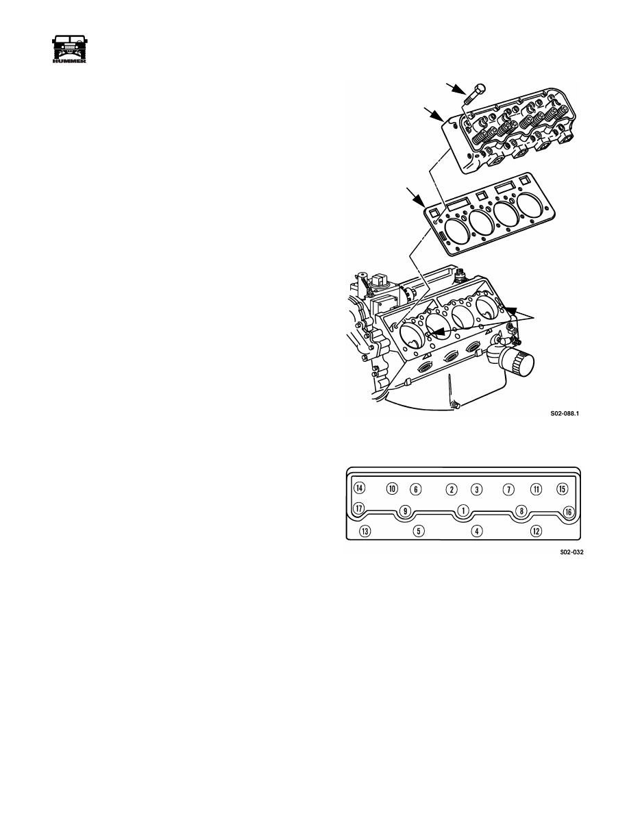
Place each head gasket on block deck and dowels 
(Figure 2-176).

2.

Carefully position each cylinder head on gasket and on
dowels (Figure 2-176).

CAUTION:  Follow torque sequence for head bolts. This is
necessary for correct compression of head gasket. Failure to
do so will cause leaks.

NOTE: Use the correct fastener in the correct location. Do not
use paints, lubricants, or corrosion inhibitors on fasteners or
fastener joint surfaces unless specified. These coatings affect
torque and joint clamping force and may damage the fastener.
Use the correct tightening sequence and specifications when
installing fasteners in order to avoid damage to parts and sys-
tems.

3.

Install cylinder head bolts as follows:

a.

Apply Loctite 592 pipe thread sealant to bolt threads
and under bolt heads.

b.

Tighten bolts in sequence  (Figure 2-177), to 20 lb-ft 
(25 N•m) torque.

c.

Repeat bolt tightening sequence to a torque of 55 lb-ft 
(75 N•m).

d.

Retighten bolts in sequence to 55 lb-ft (75 N•m).

e.

Tighten bolts an additional 90-100 degrees (1/4 plus 
turn).

Figure 2-176:   Cylinder Head and Gasket 

Installation

Figure 2-177:   Cylinder Head Bolt Tightening 

Sequence

CYLINDER HEAD

GASKET

DOWELS

HEAD

HEAD BOLT

2-90

Engine

_____________________________________________________________________

®

GLOW PLUG AND INJECTION NOZZLE 
INSTALLATION

1.

Install glow plugs in each cylinder head (Figure 2-178). 
Tighten plugs to 8-12 lb-ft (11-16 N•m).

Figure 2-178:   Glow Plug Installation

2.

Install gasket on each injector nozzle (Figure 2-179).

3.

Install injector nozzles in cylinder heads finger tight.

4.

Tighten nozzles to 44-60 lb-ft (60-81 N•m) torque with
installer tool J–29873.

5.

Connect return hoses between nozzles and install hose
clamps.

6.

Install plug on rear nozzle and install hose clamp.

Figure 2-179:   Fuel Injector Nozzle Installation

PUSHROD, ROCKER ARM AND SHAFT 
INSTALLATION

NOTE: The rocker arm end of each pushrod is identified with
a paint stripe. In addition, the ball at this end of the pushrod is
heat treated/coated giving it a distinctive color. Be sure the
pushrods are installed with the correct end up and toward the
rocker arm.

1.

Insert pushrods in roller lifters. Verify that all pushrods are 
correctly installed.

2.

Index crankshaft and pistons for rocker arm shaft
installation as follows:

a.

Position breaker bar and socket on crankshaft damper
bolt. Do not use starter to rotate crankshaft. Turn shaft
with hand tools only.

b.

Rotate crankshaft counterclockwise, and align mark
on torsional damper with “O” mark on front cover
timing tab (Figure 2-180).

c.

Rotate engine counterclockwise an additional 3 1/2
inches (89 mm), measured at mark on torsional
damper. Damper mark should align with water pump
first, lower attaching bolt at this point  (Figure 2-176).

3.

Align and install rocker arm and shaft assemblies
(Figure 2-181). Be very sure pushrods are seated in lifter
and in rocker arms. Also be sure rocker arm retainers are
in place and seated.

4.

Install rocker arm shaft retainers and bolts. Tighten bolts
in small increments until snug, with socket and ratchet or
nut runner.

CAUTION: Do not use an air wrench to tighten the bolts. In
addition, stop tightening if the bolts become hard to turn be-
fore they are seated. If this condition occurs, the crankshaft
and pistons are not properly indexed, allowing the valves to
contact the pistons.

5.

Verify that pushrods are properly seated in rocker arms
and lifters. Then final-tighten rocker arm shafts bolts to
41-lb-ft (56 N•m) torque.

GLOW PLUG

INJECTOR NOZZLE

HOSE CLAMPS

PLUG

RETURN HOSES

GASKET

____________________________________________________________________

 Engine  2-91

®

05745159

ROCKER COVER INSTALLATION

1.

Clean mounting flanges on both rocker covers and cylin-
der heads. Wipe flange sealing surfaces off with isopropyl 
alcohol to prepare surface for sealer application.

2.

Apply RTV-type sealer to cover sealing surfaces.

3.

Align and install covers on cylinder heads (Figure 2-182).

4.

Install cover attaching bolts and studs and tighten to 13-25
lb-ft (18-34 N•m). Tighten fasteners starting at center and
working toward each end.

5.

Install all necessary fuel line and wire harness brackets on
covers.

Figure 2-180:   Crankshaft Index Position for Rocker 

Arm Installation

Figure 2-181:   Rocker Arm and Shaft Installation

Figure 2-182:   Rocker Cover Installation

WATER PUMP FIRST

LOWER BOLT

O(TDC) MARK

ON TIMING TAB

3.5 in.

(89 mm)

PUSHROD

RETAINER

ROCKER

ARM AND

SHAFT

ASSEMBLY

FUEL LINE

SUPPORT BRACKET

ROCKER COVER

S02-084

2-92

Engine

_____________________________________________________________________

®

FUEL INJECTOR LINE INSTALLATION

1.

Flush injector lines with fresh diesel fuel and compressed air.

2.

Attach fuel lines to injectors and pump. Verify line routing
and connection (Figures 2-183  and 2-184).

3.

Tighten fuel line fittings at injectors and at pump to 19 lb-
ft (25 N•m) torque.

4.

Install clips on injector lines (if removed).

5.

Attach injector line clips to rocker covers.

6.

Install boot over injection line fittings at pump.

Figure 2-183:   Fuel Injector Line Layout 

Figure 2-184:   Fuel Connections at Pump

WATER CROSSOVER INSTALLATION

1.

Apply Permatex #2 to crossover gaskets and position gas-
kets on cylinder heads (Figure 2-185).

2.

If new crossover is being installed, transfer hose fittings to
new crossover. Use Loctite PST on fitting threads.

3.

Connect bypass hose to water pump (Figure 2-185).

4.

Install crossover. Tighten cross-to-cylinder head bolts/
studs to 25-37 lb-ft (34-50 N•m).

5.

Connect bypass hose to crossover hose fittings on
crossover (Figure 2-185).

6.

Install thermostat, gasket and housing on water crossover.
Apply Permatex #2 to gasket before installation and
tighten housing bolts to 31 lb-ft (42 N•m) torque.

Figure 2-185:   Water Crossover Installation

EXHAUST MANIFOLD INSTALLATION

1.

Position gasket on manifold. Then insert 1-2 bolts through 
manifold to hold gasket in place.

2.

Install manifold attaching bolts finger tight.

3.

Verify that gaskets are properly aligned. Tighten manifold
bolts to 18-25 lb-ft (24-34 N•m) torque.

CYL NO. 1

CYL NO. 8

CYL NO. 7

CYL NO. 6

CYL NO. 5

CYL NO. 4

CYL NO. 3

CYL NO. 2

CYL NO. 1

CYL NO. 8

CYL NO. 7

CYL NO. 6

CYL NO. 5

CYL NO. 4

CYL NO. 3

CYL NO. 2

GASKET

BYPASS HOSE

GASKET

WATER 

CROSSOVER


Content   ..  30  31  32  33   ..