Honda Ridgeline. Manual - part 425


  Index      Honda     Honda Ridgeline - service repair manual 2006-2008 year


Search            


Content   ..  423  424  425  426   ..


Honda Ridgeline. Manual - part 425


02

SJC8AH7G24100012701FEAT00
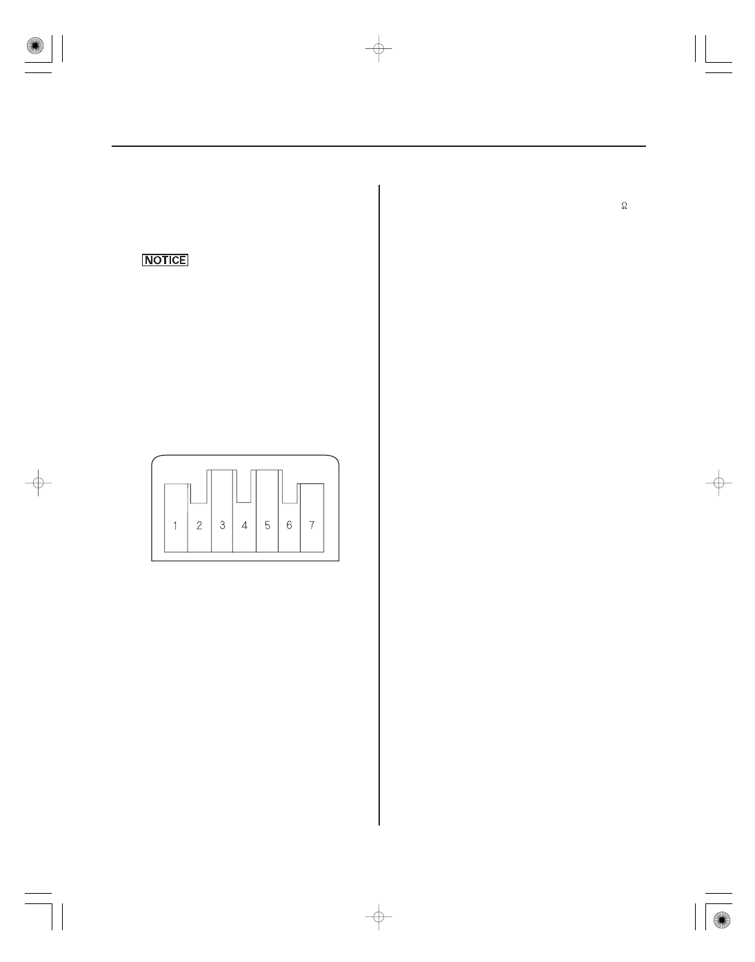
Max Cool:

About 1.5 V

Max Hot:

About 4.5 V

21-136

Climate Control

Passenger’s Air Mix Control Motor Test

PASSENGER’S AIR MIX CONTROL MOTOR

NOTE: Before testing, check for HVAC DTCs (see page
21-8).

1. Disconnect the 7P connector from the passenger’s

air mix control motor.

Incorrectly applying power and ground to
the passenger’s air mix control motor will
damage it. Follow the instructions carefully.

2. Connect battery power to the No. 1 terminal of the

passenger’s air mix control motor, and ground the
No. 2 terminal; the passenger’s air mix control
motor should run, and stop at Max Cool. If it
doesn’t, reverse the connections; the passenger’s
air mix control motor should run, and stop at Max
Hot. When the passenger’s air mix control motor
stops running, disconnect battery power
immediately.

3. If the passenger’s air mix control motor did not run

in step 2, remove it, then check the passenger’s air
mix control linkage and door for smooth
movement.

• If the linkage and door move smoothly, replace

the passenger’s air mix control motor (see page
21-137).

• If the linkage or door sticks or binds, repair them

as needed.

• If the passenger’s air mix control motor runs

smoothly, go to step 4.

4. Measure the resistance between the No. 5 and

No. 7 terminals. It should be between 4.2 to 7.8 k

.

5. Reconnect the passenger’s air mix control motor 7P

connector, then turn the ignition switch ON (II).

6. Using the backprobe set, measure the voltage

between the No. 3 and No. 7 terminals.

7. If either the resistance or voltage readings are not

as specified, replace the passenger’s air mix
control motor (see page 21-137).

03

SJC8AH7G24100012701KBAT02

01

SJC8AH7G10500016711KDAT00

21-137

21-137

Passenger’s Air Mix Control Motor
Replacement

Climate Control Unit Removal/
Installation

A

B

A

1. Open the glove box. Remove the damper and the

glove box stop on each side, then let the glove box
hang down (see page 20-85).

2. Disconnect the 7P connector (A) from the

passenger’s air mix control motor. Remove the
self-tapping screws and the passenger’s air mix
control motor (B) from the heater unit.

3. Install the motor in the reverse order of removal.

Make sure the pin on the motor is properly
engaged with the linkage. After installation, make
sure the motor runs smoothly.

1. Remove the instrument panel (see page 20-81).

2. Remove the self-tapping screws and the climate

control unit (A).

3. Install the control unit in the reverse order of

removal. After installation, operate the various
functions to see whether works properly.

4. Run the self-diagnostic function to confirm that

there are no problems in the system (see page
21-83).

SJC8A000000000J2201ABAT00

SUPPLEMENTAL RESTRAINT SYSTEM (SRS) (If electrical maintenance is required)

The Ridgeline SRS includes a driver’s airbag in the steering wheel hub, a passenger’s airbag in the dashboard above
the glove box, seat belt tensioners in the front seat belt retractors, side curtain airbags in the sides of the roof, and side
airbags in the front seat-backs. Information necessary to safely service the SRS is included in this Service Manual.
Items marked with an asterisk (

) on the contents page include or are located near SRS components. Servicing,

disassembling, or replacing these items requires special precautions and tools, and should be done by an authorized
Honda dealer.

• To avoid rendering the SRS inoperative, which could lead to personal injury or death in the event of a severe frontal

or side collision, all SRS service work should be done by an authorized Honda dealer.

• Improper service procedures, including incorrect removal and installation of the SRS, could lead to personal injury

caused by unintentional deployment of the airbags and/or side airbags.

• Do not bump or impact the SRS unit, front impact sensors, or side impact sensors when the ignition switch is ON (II),

or for at least 3 minutes after the ignition switch is turned OFF; otherwise, the system may fail in a collision, or the
airbags may deploy.

• SRS electrical connectors are identified by yellow color coding. Related components are located in the steering

column, front console, dashboard, dashboard lower panel, in the dashboard above the glove box, in the front seats,
in the roof side, and around the floor. Do not use electrical test equipment on these circuits.

SJC8A000000000J2201ZCAT00

Body Electrical

Body Electrical

.........................

.........................

Relay and Control

Unit Locations

. 22-7

........

........

Connectors and Harnesses

. 22-15

........................

........................

Fuse/Relay Boxes

. 22-60

......................

......................

Power Distribution

. 22-64

....................

....................

Ground Distribution

. 22-68

Under-hood Fuse/Relay Box

......

......

Under-dash Fuse/Relay Box

. 22-73

Battery

Relays

Ignition Switch

Multiplex Integrated Control System

Keyless/Power Door Locks/Security

System

Horns

Exterior Lights

Dash Lights Brightness Controller

Turn Signal/Hazard Warning Lights

..............................................

.....

..............................................

.....

Special Tools

. 22-2

General Troubleshooting Information

. 22-3

................................

..........................

................................

..........................

DTC Troubleshooting

. 22-69

Removal and Installation

. 22-72

.............................................................

..............................................

.............................................................

..............................................

Test

. 22-77

Replacement

. 22-77

......................

.....

......................

...................................

.........................

..........................

..........................

.........................

...........................

..........................................

................................

.........................................

............

...

...............................................

.............

......................

.....

......................

...................................

.........................

..........................

..........................

.........................

...........................

..........................................

................................

.........................................

............

...

...............................................

.............

Component Location Index

. 22-78

General Troubleshooting Information

. 22-80

DTC Troubleshooting Index

. 22-83

System Description

. 22-87

Troubleshooting-B-CAN System

Diagnosis Test Mode A

. 22-99

Troubleshooting-B-CAN System

Diagnosis Test Mode B

. 22-100

Troubleshooting-B-CAN System

Diagnosis Test Mode C

. 22-101

Troubleshooting-B-CAN System

Diagnosis Test Mode D

. 22-102

Troubleshooting-B-CAN System

Diagnosis Test 1 and 2

. 22-103

Circuit Diagram

. 22-106

DTC Troubleshooting

. 22-108

MICU Input Test

. 22-117

Gauge Control Module Input Test

. 22-122

Door Multiplex Control Unit Input Test

. 22-123

Combination Switch Control Unit

Input Test

. 22-124

Relay Control Module Input Test

. 22-125

......................

...................................

..........................................

................................

......................

..............................

...........................

.....................

.................

...............................

.......................................

.......

.............................................

........................................

......................

...................................

..........................................

................................

......................

..............................

...........................

.....................

.................

...............................

.......................................

.......

.............................................

........................................

Component Location Index

. 22-126

System Description

. 22-128

Circuit Diagram

. 22-130

DTC Troubleshooting

. 22-133

Symptom Troubleshooting

. 22-138

Control Unit Input Test

. 22-139

Door Lock Actuator Test

. 22-146

Door Lock Knob Switch Test

. 22-147

Door Key Cylinder Switch Test

. 22-148

Door Lock Switch Test

. 22-149

Hood Switch Test

. 22-149

Security Indicator Test/Replacement

. 22-150

In-Bed Trunk Lid Key Cylinder

Switch Test

. 22-150

Transmitter Test

. 22-151

......................

..........................................

............................

.......................................

......................

..........................................

............................

.......................................

Component Location Index

. 22-154

Circuit Diagram

. 22-155

Horn Test/Replacement

. 22-155

Horn Switch Test

. 22-156

......................

..........................................

................................

.............

...................

...............................

.............................

.....................................

...............................

.............

.....

................

..........

........

.............

Component Location Index

. 22-157

Circuit Diagram

. 22-160

DTC Troubleshooting

. 22-168

Brake Pedal Position Switch Test

. 22-174

Cargo Area Light Switch Test

. 22-174

Headlight Adjustment

. 22-175

Headlight Replacement

. 22-176

Bulb Replacement

. 22-177

Taillight Replacement

. 22-178

License Plate Light Replacement

. 22-178

High Mount Brake Light Replacement

. 22-179

Cargo Area Light Replacement

. 22-180

In-Bed Trunk Lid Latch Switch Test

. 22-180

Headlight Switch Test/Replacement

. 22-181

Tailgate Switch

Test/Replacement/Adjustment

. 22-182

..........................................

...........................................

..........................................

...........................................

Circuit Diagram

. 22-183

Controller Test

. 22-184

......................

..........................................

.......

..................................

......................

..........................................

.......

..................................

Component Location Index

. 22-185

Circuit Diagram

. 22-186

Turn Signal/Hazard Relay Input Test

. 22-188

Hazard Warning Switch

Test/Replacement

. 22-190

................................

.................................

22-74

Battery Test

................................

................................. 22-75

Power Relay Test

..........

..........

....

....

..

...

...

..

..

..

..

..

Deleting - Manual Method 

Keyless Transmitter Programming/

.................

..................

.

. 22-153


Content   ..  423  424  425  426   ..