Honda Odyssey 2004. Manual - part 463
*01
S0X4A00J34300044051EAAT25
−
−
22-180
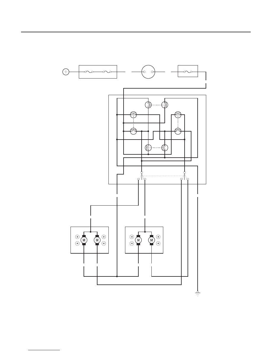
Power Mirrors
Circuit Diagram - without Defogger
POWER MIRROR SWITCH
4
1
YEL/BLK
DOWN
RIGHT
LEFT
UP
2
10
9
8
7
RIGHT
LEFT
LEFT
RIGHT
No.4 (7.5A)
YEL
IGNITION SWITCH
IG2
BAT
BLU/WHT
BLU/GRN
YEL/WHT
BLU/ORN
BLU/WHT
BLU/WHT
UNDER HOOD FUSE/RELAY BOX
LEFT MIRROR
RIGHT MIRROR
2
2
1
3
3
1
UP
RIGHT
LEFT
DOWN
DOWN
LEFT
RIGHT
UP
LT GRN
G501
BLK
WHT
No.42 (50A)
No.41 (120A)
BATTERY
DRIVER’S
UNDER DASH
FUSE/RELAY BOX
03/07/29 10:22:49 61S0X050_220_0182