Honda Odyssey 2004. Manual - part 383


  Index      Honda     Honda Odyssey 2004 - service repair manual 2004 year


Search            


Content   ..  381  382  383  384   ..


Honda Odyssey 2004. Manual - part 383


01

S0X4A11G10100000000BBAT10

How to Retrieve a DTC

Cancelling the Self-diagnosis Function

21-8

Heating/Air Conditioning

General Troubleshooting Information

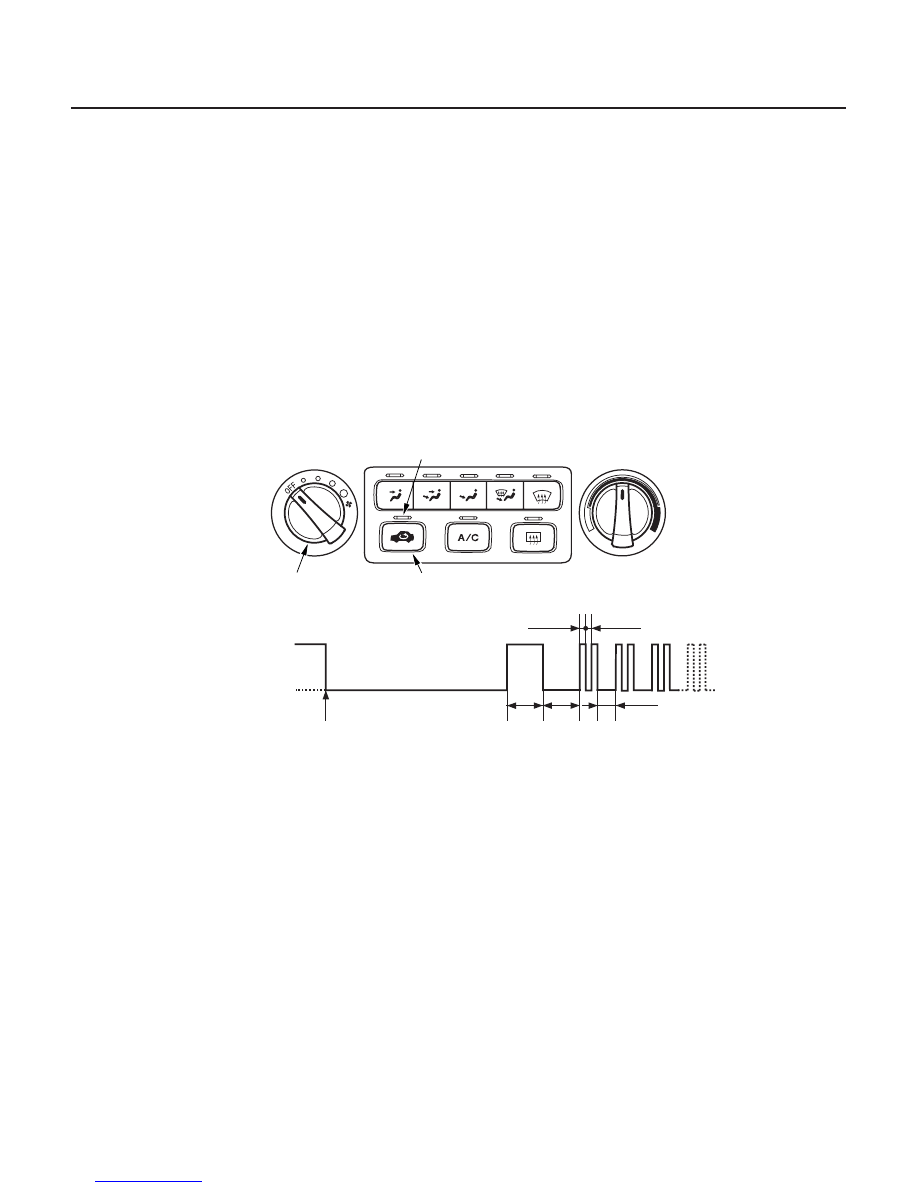
RECIRCULATION INDICATOR

FAN SWITCH

RECIRCULATION CONTROL BUTTON

Example of DTC Indicator Pattern (DTC 2):

Recirculation
indicator on

Recirculation
indicator off

Press and hold the
recirculation
control button

0.3 sec

2 sec

1 sec

2 sec

0.3 sec

The heater control panel has a self-diagnosis function. To run the self-diagnosis function, do the following:

1. Turn the ignition switch ON (II).

2. Turn the fan switch OFF.

3. Press the recirculation control button to select Recirculation (recirculation indicator comes on).

4. Press and hold the recirculation control button to select Fresh (recirculation indicator goes off). Continue to hold

the button until the recirculation indicator comes on for 2 seconds, and then goes off.

• If the system is OK, the recirculation indicator stays off.
• If any trouble is found, the recirculation indicator blinks the diagnostic trouble code (DTC) to indicate faulty

circuit or component.

5. Turn the ignition switch OFF to cancel the self-diagnosis function. After completing repair work, run the self-

diagnosis function again to make sure that there are no other malfunctions.

03/07/29 10:09:45 61S0X050_210_0009

S0X4A11G10100000000GAAT00

DTC

(Recirculation

Indicator Blinks)

Detection Item

Page

21-9

DTC Troubleshooting Index

1

A problem in the air mix control motor circuit

(see page 21-16)

2

A problem in the mode control motor circuit

(see page 21-17)

3

A problem in the evaporator temperature sensor circuit

(see page 21-19)

• In case of multiple problems, the recirculation indicator will indicate only the DTC with the least number of blinks.
• In case of an intermittent failure, the heater control panel will store the DTC unit the ignition is turned off.

03/07/29 10:09:45 61S0X050_210_0010

S0X4A11G10100000000HBAT01

Symptom

Diagnostic procedure

Also check for

21-10

Heating/Air Conditioning

Symptom Troubleshooting Index


Recirculation control doors do not
change between Fresh and
Recirculate.

Recirculation control motor
circuit troubleshooting (see
page 21-21)

HVAC DTCs (see page 21-8)
Blown fuse No. 3 (7.5A) in the driver’s under-
dash fuse/relay box
Cleanliness and tightness of all connectors

Blower motor runs, but one or
more speeds do not work.

Blower motor circuit
troubleshooting (see page
21-22)

HVAC DTCs (see page 21-8)
Blown fuse No. 56 (40A) in the under-hood
fuse/relay box, and No. 3 (7.5A) in the driver’s
under-dash fuse/relay box
Poor ground at G201 and G401
Cleanliness and tightness of all connectors

Blower motor does not run at all.

Blower motor circuit
troubleshooting (see page
21-22)

HVAC DTCs (see page 21-8)
Blown fuse No. 56 (40A) in the under-hood
fuse/relay box, and No. 3 (7.5A) in the driver’s
under-dash fuse/relay box
Poor ground at G201 and G401
Cleanliness and tightness of all connectors

Blower, heater controls, and A/C
do not work.

Heater control power and
ground circuit
troubleshooting (see page
21-26)

HVAC DTCs (see page 21-8)
Blown fuse No. 54 (40A) in the under-hood
fuse/relay box, No. 3 (7.5A) in the driver’s
under-dash fuse/relay box, and No. 13 (7.5A)
in the passenger’s under-dash fuse/relay box
Poor ground at G401
Cleanliness and tightness of all connectors

Both fans do not run at low speed
with the A/C on when the
refrigerant pressure is below
1,520 kPa (15.5 kgf/cm , 220 psi).

Radiator and condenser fan
low speed circuit
troubleshooting (see page
21-27)

HVAC DTCs (see page 21-8)
Blown fuse No. 58 (30A) in the under-hood
fuse/relay box, and No. 3 (7.5A) in the driver’s
under-dash fuse/relay box
Poor ground at G201
Cleanliness and tightness of all connectors

Condenser fan does not run at
high speed when the engine
coolant temperature is above
210°F (99°C) or the refrigerant
pressure is above 1,520 kPa
(15.5 kgf/cm , 220 psi) with the A/C
on.

Condenser fan high speed
circuit troubleshooting (see
page 21-30)

HVAC DTCs (see page 21-8)
Blown fuse No. 3 (7.5A) in the driver’s under-
dash fuse/relay box
Poor ground at G201
Cleanliness and tightness of all connectors

Both fans do not run at high speed
with the A/C on when the
refrigerant pressure is above
1,520 kPa (15.5 kgf/cm , 220 psi).

Radiator and condenser fan
high speed circuit
troubleshooting (see page
21-31)

HVAC DTCs (see page 21-8)
Cleanliness and tightness of all connectors

Compressor clutch does not
engage. (but both fans run with
the A/C on)

Compressor clutch circuit
troubleshooting (see page
21-32)

HVAC DTCs (see page 21-8)
Blown fuse No. 59 (7.5A) in the under-hood
fuse/relay box, and No. 3 (7.5A) in the driver’s
under-dash fuse/relay box
Cleanliness and tightness of all connectors

A/C system does not come on
(both fans and compressor do not
work); heater is OK.

A/C pressure switch circuit
troubleshooting (see page
21-35)

HVAC DTCs (see page 21-8)
Cleanliness and tightness of all connectors

2

2

2

03/07/29 10:09:45 61S0X050_210_0011

*04

S0X4A11G10100000000CAAT10

21-11

System Description

EVAPORATOR EXPANSION VALVE

RECEIVER/DRYER

A/C COMPRESSOR

CONDENSER

A/C PRESSURE SWITCH

BLOWER FAN

EVAPORATOR

EVAPORATOR TEMPERATURE
SENSOR

A/C COMPRESSOR RELIEF VALVE

HIGH PRESSURE VAPOR

HIGH PRESSURE LIQUID

LOW PRESSURE LIQUID

LOW PRESSURE VAPOR

The air conditioning system removes heat from the passenger compartment by circulating refrigerant through the
system as shown below.

This vehicle uses HFC-134a (R-134a) refrigerant which does not contain chlorofluorocarbons. Pay attention to the
following service items:

• Do not mix refrigerants CFC-12 (R-12) and HFC-134a (R-134a). They are not compatible.
• Use only the recommended polyalkyleneglycol (PAG) refrigerant oil (DENSO ND-OIL 8) designed for the R-134a

compressor. Intermixing the recommended (PAG) refrigerant oil with any other refrigerant oil will result in
compressor failure.

• All A/C system parts (compressor, discharge line, suction line, evaporator, condenser, receiver/dryer, expansion

valve, O-rings for joints) are designed for refrigerant R-134a. Do not exchange with R-12 parts.

• Use a halogen gas leak detector designed for refrigerant R-134a.
• R-12 and R-134a refrigerant servicing equipment are not interchangeable. Use only a recovery/recycling/charging

station that is U.L.-listed and is certified to meet the requirements of SAE J2210 to service R-134a air conditioning
system.

• Always recover the refrigerant R-134a with an approved recovery/recycling/charging station before disconnecting

any A/C fitting.

(cont’d)

(Meters the required amount of
refrigerant into the evaporator)

(Traps debris, and
removes moisture)

(Suction and compression)

(Radiation of heat)

(Triple function)
When the refrigerant is below
196 kPa (2.0 kgf/cm , 28 psi)
or above 3,140 kPa (32 kgf/cm ,
455 psi), the A/C pressure
switch opens the circuit to
the A/C switch and stops the
air conditioning to protect the
compressor.
When the refrigerant is above
1,520 kPa (15.5 kgf/cm ,
220 psi), the A/C pressure
switch switches the radiator and
condenser fans to high speed.

(Absorption of heat)

(Relieves pressure at the
compressor when the
pressure is too high)

2

2

2

03/07/29 10:09:46 61S0X050_210_0012


Content   ..  381  382  383  384   ..