Honda Odyssey 2004. Manual - part 229
*01
*02
↓
↓
↓
↓
↓
↓
↓
↓
↓
↓
↓
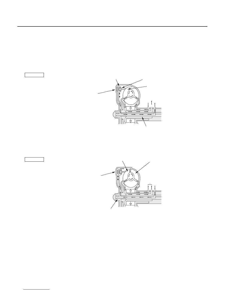
Lock-up System
Torque Converter Clutch Lock-up ON (Engaging Torque Converter Clutch)
Torque Converter Clutch Lock-up OFF (Disengaging Torque Converter Clutch)
14-310
Automatic Transmission
System Description (cont’d)
Power flow
The power flows by way of:
Engine
Drive plate
Torque converter cover
Torque converter clutch piston
Damper spring
Turbine
Mainshaft
MAINSHAFT
TURBINE
DAMPER SPRING
TORQUE CONVERTER
CLUTCH PISTON
TORQUE CONVERTER
COVER
To ATF cooler
INLET
OUTLET
Power flow
Engine
Drive plate
Torque converter cover
Pump
Turbine
Mainshaft
MAINSHAFT
TURBINE
TORQUE CONVERTER
COVER
PUMP
To ATF cooler
INLET
Fluid in the chamber between the torque converter cover and the torque converter clutch piston is drained off, and
fluid entering from the chamber between the pump and stator exerts pressure through the torque converter clutch
piston against the torque converter cover. The torque converter clutch piston engages with the torque converter cover;
torque converter clutch lock-up ON, and the mainshaft rotates at the same as the engine.
Fluid entered from the chamber between the torque converter cover and the torque converter clutch piston passes
through the torque converter and goes out through the chambers between the turbine and the stator, and between the
pump and the stator. As a result, the torque converter clutch piston moves away from the torque converter cover, and
the torque converter clutch lock-up is released; torque converter clutch lock-up OFF.
03/07/29 09:38:50 61S0X050_140_0313